
Oct 8, 2026Buying Guides
Control Panel Line Reactor and Harmonic Filter: When Your VFD Panel Actually Needs One
A line reactor isn't something you bolt on every VFD by reflex. Here's the engineering case for when your VFD panel actually needs one — and when it doesn't.
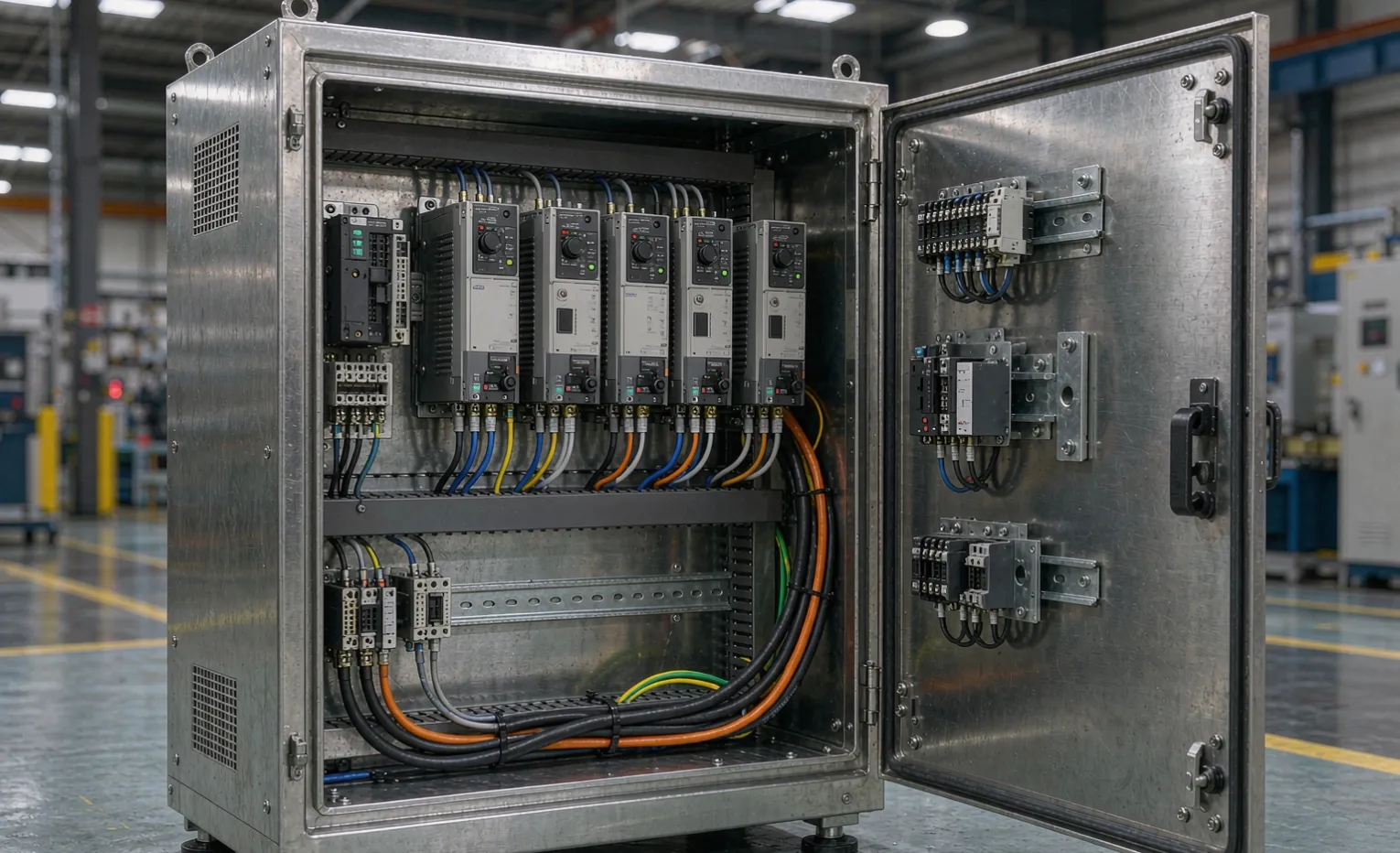
I get asked to add a line reactor to every VFD panel I quote. Nine times out of ten, that's the wrong reflex. A line reactor—or its cousins, the DC bus choke and the active harmonic filter—is a fix for a specific problem: current harmonics and voltage spikes riding back into your supply. If your supply is clean and your drive-to-source ratio is low, you're adding cost, heat, and panel space for nothing.
Here's how to tell which camp your panel is in, and what to actually write into the RFQ.
What a VFD does to the supply
A VFD rectifies incoming AC to DC, then chops it back to variable-frequency AC for the motor. That front-end rectifier doesn't draw a clean sine wave—it draws current in short pulses at the voltage peaks. Stack enough of those pulses on one feeder and the supply voltage develops notches and flat-tops, and some of that distortion flows backward onto the bus.
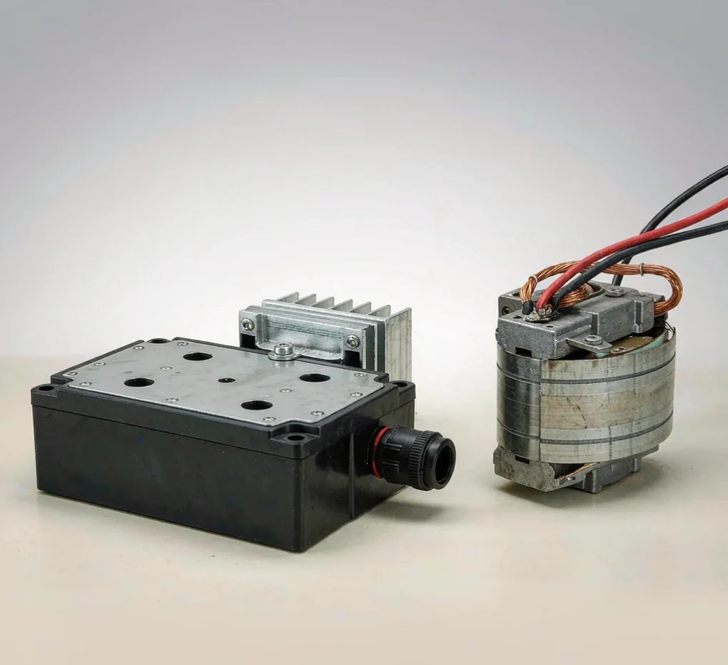
The standard that governs this for adjustable-speed drives is IEC 61800-3; in North America the panel-build side sits under UL 508A, and the drive-product side under NEMA ICS 7.1 / NEMA MG 1. None of them say "put a reactor on every drive." They set limits, and the reactor is one way to stay inside them.

The symptoms that say "yes, you need one"
A reactor earns its place when the supply can't absorb what the drives are pushing back. Four tells:
Your transformer or generator is undersized for the drives.
Rule of thumb from the field: once total VFD power climbs past roughly 10–15% of the feeding transformer's kVA, harmonic current starts to bite. On a generator supply, the threshold is lower—generators hate the notching.
You're tripping on the input side, not the drive.
If upstream breakers, a neighboring soft starter, or PF capacitors nuisance-trip when the drives run, you're seeing the distortion, not a drive fault.
You share the bus with sensitive neighbors.
A weigh scale that drifts, a PLC analog input that wanders, and comms errors that only appear when the big VFDs spin up—that's harmonic cross-talk on a shared point of common coupling.
You have power-factor capacitors upstream.
This is the quiet killer. A reactor changes the resonant frequency of the circuit. Add drives without checking, and you can push the system into resonance that overheats or fails the capacitors. NEMA guidance on drive systems treats this as a real design step, not an afterthought.
The three fixes, and what each one earns
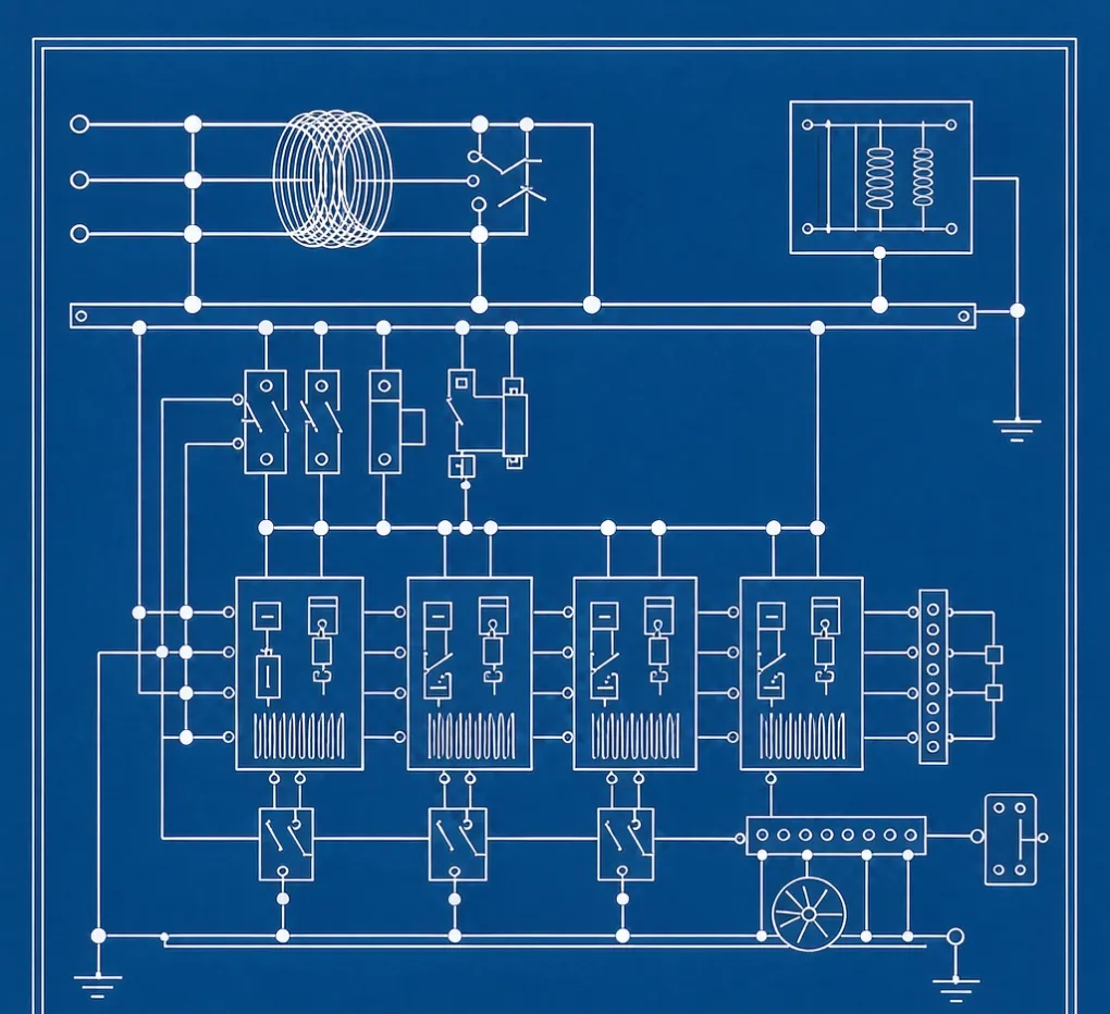
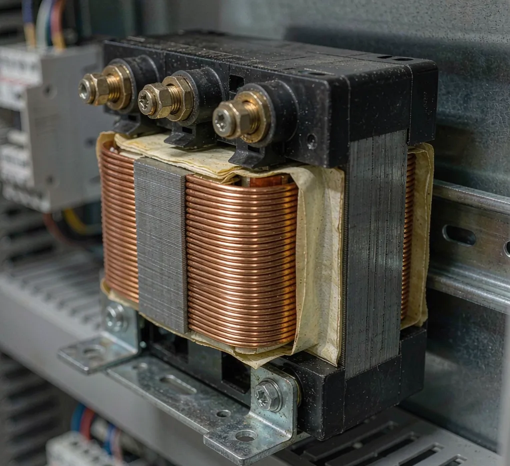
Input line reactor (AC inductor). A ~3% impedance choke at the VFD input. It smooths the current pulses, roughly halves the 5th and 7th harmonic current, and absorbs voltage spikes and dv/dt from the line. Cheap, passive, always on. This is the workhorse.
DC bus choke. Many drives already build this in. It attacks the harmonic current at the source, inside the drive, so it does some of the reactor's job—but only if the drive actually has one rated for it.
Active front end / harmonic filter. For strict utility limits or a generator-dominated site, this drives total harmonic distortion down to low single digits per IEC 61800-3. It's the expensive option, and you only reach for it when the cheaper ones won't pass.
Condition | What to specify |
|---|---|
Drive load under ~10% of transformer kVA, clean supply. | Nothing extra—rely on the drive's built-in DC choke. |
10–30% ratio, mild notching | 3% input line reactor on the larger drives |
Shared bus with sensitive loads or flicker | Line reactor + a resonance check against PF capacitors |
Utility THD limit or generator supply | Active harmonic filter, sized to IEC 61800-3 |
A build we scoped
An OEM packaging line ran on a 500 kVA transformer with about 90 HP of VFDs across three panels — roughly 13% of transformer capacity, right in the zone. The first quote had no reactor. The plant had intermittent analog drift on a neighbouring weigh scale that nobody could pin down. We added 3% input reactors on the two largest drives, and the drift stopped. It was a line item, not a rebuild — and it cost less than one service call to chase the "ghost" fault.
The cheap move would have been to spec it at the RFQ stage. The expensive move was learning the hard way.
Mistakes buyers make
- "Add a reactor to every drive by default." You're paying for iron, heat, and panel space you may not need. Spec it where the ratio says so.
- "The drive's built-in filtering is always enough." Only true below the threshold. Past it, the built-in choke barely dents the problem.
- "Harmonics are someone else's problem." They're not — they show up as trips, drift, and angry neighbours on your own bus.
If your panel also needs backed-up power, the same "spec it properly, don't guess" logic applies to the UPS — our guide to what to put in an industrial UPS RFQ walks that side.
For the record, we're a sourcing partner and panel-build shop, so this is buying advice, not a parts catalogue. Our electrical enclosure supplier's guide to sourcing from China covers the whole build-and-ship process, and our custom control panels solution page shows what we build.
FAQ
Do I need a line reactor on every VFD?
No. Below roughly 10% of transformer kVA on a clean supply, the drive's own DC choke is usually enough. Add a reactor when the drive-to-source ratio, notching, or shared-bus noise says so.
What does a 3% line reactor actually do?
It adds about 3% impedance at the VFD input, smoothing the pulsed rectifier current, roughly halving the 5th and 7th harmonics, and absorbing line spikes and dv/dt that would otherwise stress the drive.
Line reactor or DC bus choke—which one?
They're complementary. If the drive already has a rated DC choke and you're just below the threshold, that may suffice. For input-side protection against spikes and resonance, the AC input reactor is the broader fix.
Will a line reactor stop my VFD tripping on a ground fault?
No—ground-fault tripping is a different problem (often grounding, cabling, or drive setup). A reactor handles harmonics and voltage transients, not insulation faults.
How do I know harmonics are actually my problem?
Look for upstream nuisance tripping when drives run, analog/comm-drift on a shared bus, or capacitor overheating. A power-quality meter at the point of common coupling gives you the THD numbers to confirm.
Does UL 508A require a line reactor?
No. UL 508A governs how the panel is built and protected; it doesn't mandate harmonic mitigation. That's an application decision driven by your supply and load.
Engineering takeaway
A line reactor isn't a reflex — it's a fix for a measured condition. Check the drive-to-transformer ratio, watch for notching and shared-bus noise, and verify you won't resonate with upstream capacitors. Below ~10% ratio on a clean supply, the drive's built-in choke is enough; past it, a 3% input reactor usually does the job, and only generator or utility-limited sites need the active filter.
Related guides
- Control panel surge protection: what your spec is missing — transients ride the same wire, defend both ends
- Motor control panel supplier checklist — seven questions to ask before you order - OEM machine control panel cost drivers — what actually moves the quote
Want a second pair of eyes on a VFD panel spec you already have? Upload your drawing for an engineering review — we'll flag the harmonic and bonding gaps, then send suggestions back.