
Oct 30, 2026Buying Guides
Control Panel Power Distribution: Sizing the Busbar and Branch Taps
How power flows from the main disconnect through the busbar to the branch taps — and how to size the backbone, clearances, and SCCR so the panel doesn't overheat or fail inspection.
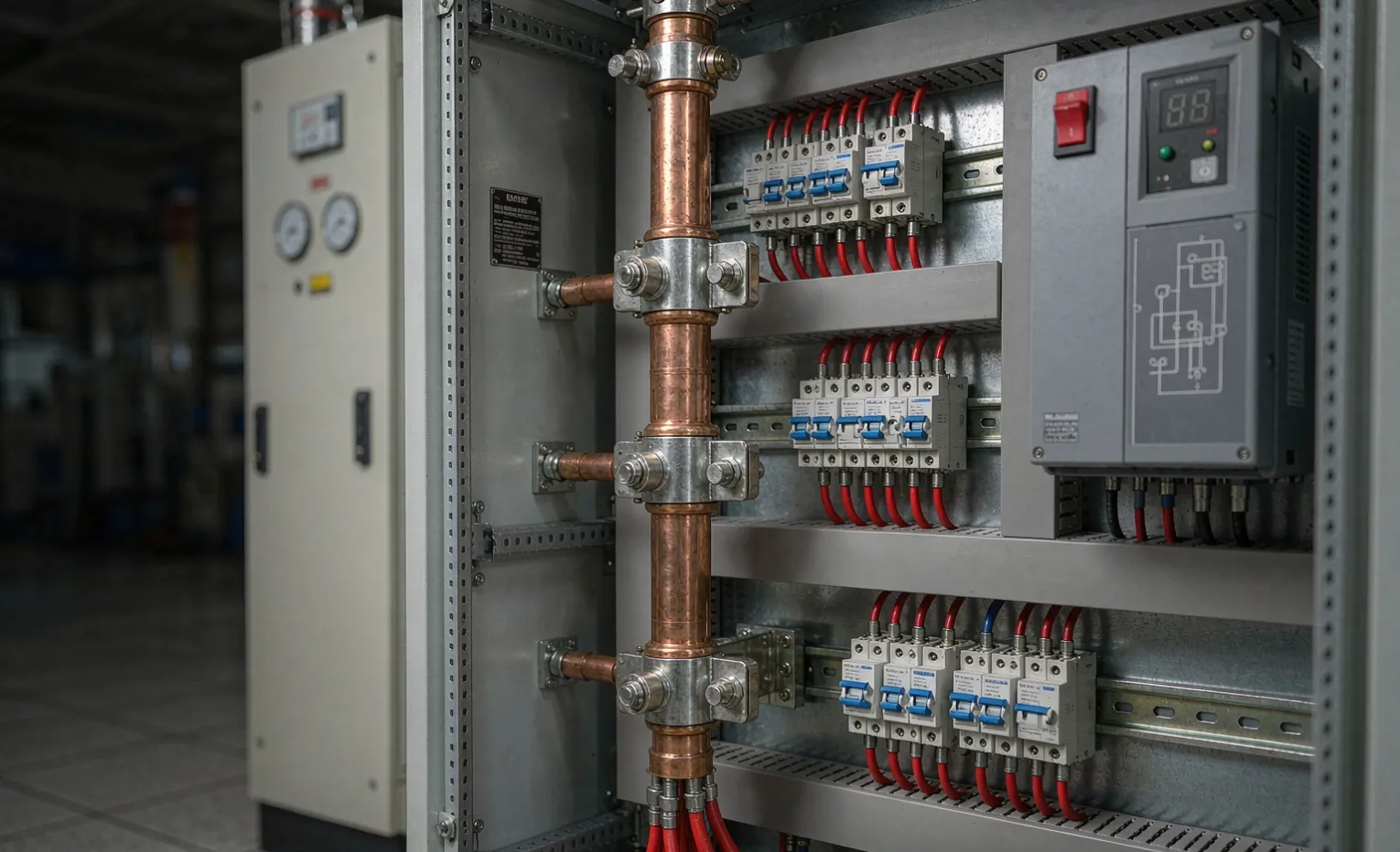
Control Panel Power Distribution: Sizing the Busbar and Branch Taps
You open a control panel and see a thick copper bar running down the back, with half a dozen smaller wires clamped to it. That bar—the busbar—is the spine of the whole panel. Get its size wrong and you either waste money on copper you didn't need, or you build a panel that runs hot, trips on heat, and fails the short-circuit withstand check at commissioning. Most panel problems I'm called in to fix trace back to a backbone that was never properly sized, not to the devices bolted to it.
Written from a sourcing-partner and panel-build perspective: we lay out and source control panels built in China, and we do not manufacture the components that go inside the panel. Our interest is that the power distribution is sized to the load and the fault level the first time, so what ships is what your site actually needs. For the sourcing approach behind how we build and source, see our electrical enclosure sourcing guide (China).
If you are still choosing the incoming disconnect itself, our control panel main disconnect guide covers switch selection. This guide picks up where that leaves off: everything downstream of the disconnect—the busbar, the distribution block, and the branch taps. And when the panel lives in a harsh site, pair this with our enclosure supplier document checklist so the enclosure around this backbone is proven, not just claimed. For the panels we build and source, see our custom control panel solutions.
Engineering Note: The busbar is not a "one size per amp" part. Its temperature rise, the fault current it can survive for a few seconds, and the spacing around it are three separate constraints — and the tightest one wins. Sizing to ampacity alone is the most common mistake.
The path power takes through the panel
Before any sizing, map the chain. A typical industrial control panel routes power like this:
- Incoming supply—line terminals from the upstream feeder.
- Main disconnect—the switch or circuit breaker that isolates the whole panel (covered in the main disconnect guide).
- Busbar or power distribution block (PDB)—the backbone that splits one incoming feed into many branch points.
- Branch protection—molded-case breakers (MCCB), fused disconnects, or motor protection switches on each derived circuit.
- Loads—VFDs, contactors, power supplies, PLC I/O, heaters.
The busbar is step 3. It is where a single 100 A or 400 A feed becomes ten 10 A and 20 A branches. The sizing work is: make the backbone carry the total without overheating, make every branch tap legal, and make the whole assembly survive the available fault current at the panel.
Vertical vs. horizontal busbar
Small panels often use a horizontal copper bar across the top, with breakers mounted below. Larger panels use a vertical busbar running floor to ceiling, with branch devices tapped off it. The orientation changes how you lay out clearances, but the sizing math is the same: continuous ampacity, temperature rise, and withstand rating.
Sizing the busbar: ampacity and temperature rise
The backbone must carry the sum of the branch loads it feeds—plus a margin for inrush and future expansion. Two numbers matter:
- Continuous ampacity—the current the bar can carry all day without exceeding its rated temperature rise. For listed busbar systems this is given by the manufacturer; for bare copper the common reference point is roughly 1000 A per square inch of cross-section at 30°C rise in open air, derated heavily once you enclose it.
- Temperature rise limit—UL 891 (switchboards) and IEC 61439-1 (low-voltage switchgear) both key on a maximum temperature rise, typically 30°C above a 40°C ambient for bare conductors. The bar isn't "rated by amps" in isolation; it's rated by how hot it gets.
Backbone choice | When it fits | Watch out. |
|---|---|---|
Single copper busbar | Panels up to ~400 A, few branches | Enclosure cooling must be real; no aluminum in our builds. |
Power distribution block (PDB) | Many branch taps off one feed, clean | Verify each tap rating, not just the block total. |
Insulated busbar (stack) | Tight panels, phase isolation needed | Cost: check creepage to enclosure wall |
Multiple parallel bars | High current in limited width | Balance current; torque both joints. |
Buyer Decision: Ask the builder for the busbar's rated continuous current and its temperature-rise limit, not just a cross-section. A bar sized by ampacity in free air can exceed its rise limit the moment you close it inside a sealed panel.
Material: copper, and why not aluminum?
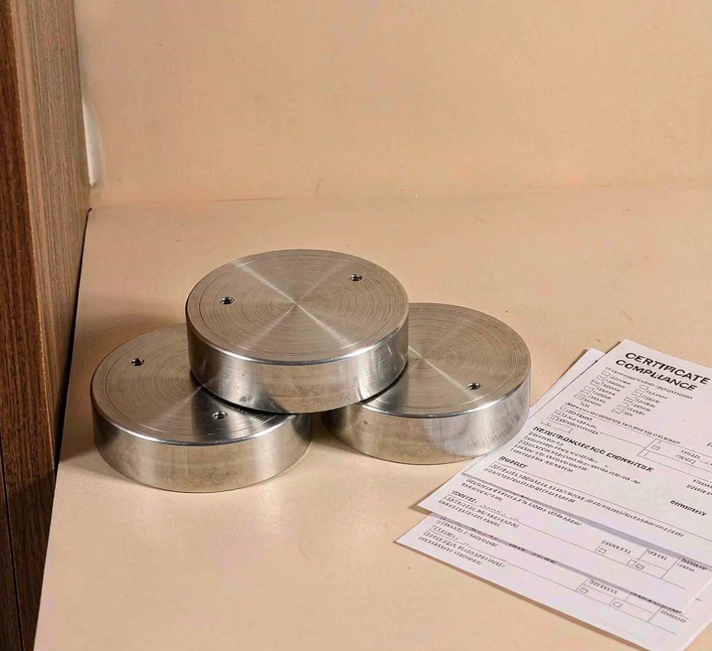
We build backbones in copper (bare or tinned) or in tinned copper for corrosive sites. We do not use aluminum busbar in these panels—the joint reliability and torque-creep behavior aren't worth the marginal material saving on a safety-critical spine. That's a deliberate policy, not a cost one.
Branch taps: the rule buyers forget
The branch wires clamped to the busbar aren't sized by the busbar's ampacity—they're sized by what they feed, and they must be tapped legally. Under UL 508A / NEC Article 409 (industrial control panels), tap conductors are permitted under specific rules: the tap must be protected at its ampacity, short enough, and terminated on a listed device. A common failure mode is a 4 AWG tap hung off a 400 A bar with no fusing at the tap point—that's a fire path, not a branch.
Coordination, not just connection
Each branch needs its own overcurrent protection sized to the load. The busbar is not the protector; it's the highway. The breakers and fuses on it do the protecting. And they must coordinate—a branch fault should trip the branch device, not the main, so you lose one circuit instead of the whole panel.
SCCR: the backbone has to survive the fault
Short-circuit current rating (SCCR) is the panel's ability to withstand the available fault current at its terminals for the few seconds before protection clears—the backbone is judged against UL 508A and the assembly against IEC 61439. The busbar and every device on it must be rated for the site's available fault current—typically 10 kA, 25 kA, 65 kA, or higher at the service. Our control panel SCCR guide walks the full label logic; the point for distribution design is simple:
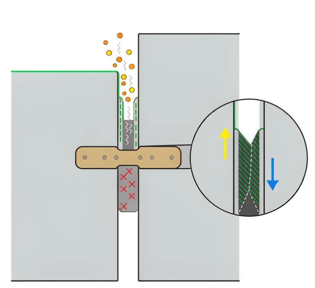
- The busbar's withstand must meet or exceed the available fault current.
- Every branch protective device must have a published interrupting rating at that level.
- A listed "combination motor controller" or "circuit breaker" with a high SCCR can pull the panel's rating up — but only if the backbone it lands on is rated to match.
Engineering Note: A 65 kA breaker landed on a busbar rated for 25 kA gives you a 25 kA panel, not a 65 kA one. The backbone sets the ceiling. Buyers who spec the breaker and ignore the bar buy a rating they don't have.
Clearances, bending space, and layout
The bar needs room to breathe and to be wired safely. Relevant rules:
- Wire bending space—NEC 312.6 and UL 508A require minimum space at terminals so a conductor can be formed without stressing the joint. Cramped panels cause loose lugs, and loose lugs cause hot joints.
- Creepage and clearance—phase-to-phase and phase-to-ground spacing must suit the system voltage. In a 480 V panel, this is tighter than in a 230 V one.
- Neutral and ground bars—separate, bonded correctly at one point only (the main bonding jumper). Mixing them downstream creates parallel ground paths and nuisance tripping.
We lay out the backbone first, then place branch devices around it with real bending space—not the other way around. A panel drawn around the busbar is serviceable; a panel with the bar squeezed in at the end is a maintenance nightmare.
Heat: the silent killer of a tight panel
Every device on the busbar—VFDs, contactors, power supplies—dumps heat into the same enclosure the bar sits in. Two heat sources add up:
- I²R loss in the bar itself at full load.
- Device heat from everything bolted nearby.
If you size the bar for ampacity but seal it in a small enclosure with three VFDs, the enclosure temperature climbs and the bar's rise limit is exceeded anyway. That's why panel cooling and thermal load is part of the same conversation as distribution design, not a separate one.
What to put in your RFQ so the backbone is right
When you ask us to build or source a panel, the distribution design is only as good as the inputs. Send:
- The incoming supply voltage, phases, and available fault current at the panel.
- The full load list with each branch's ampacity and inrush.
- Whether a UL 508A listing is required (drives the busbar and device choices) and the end customer's SCCR demand.
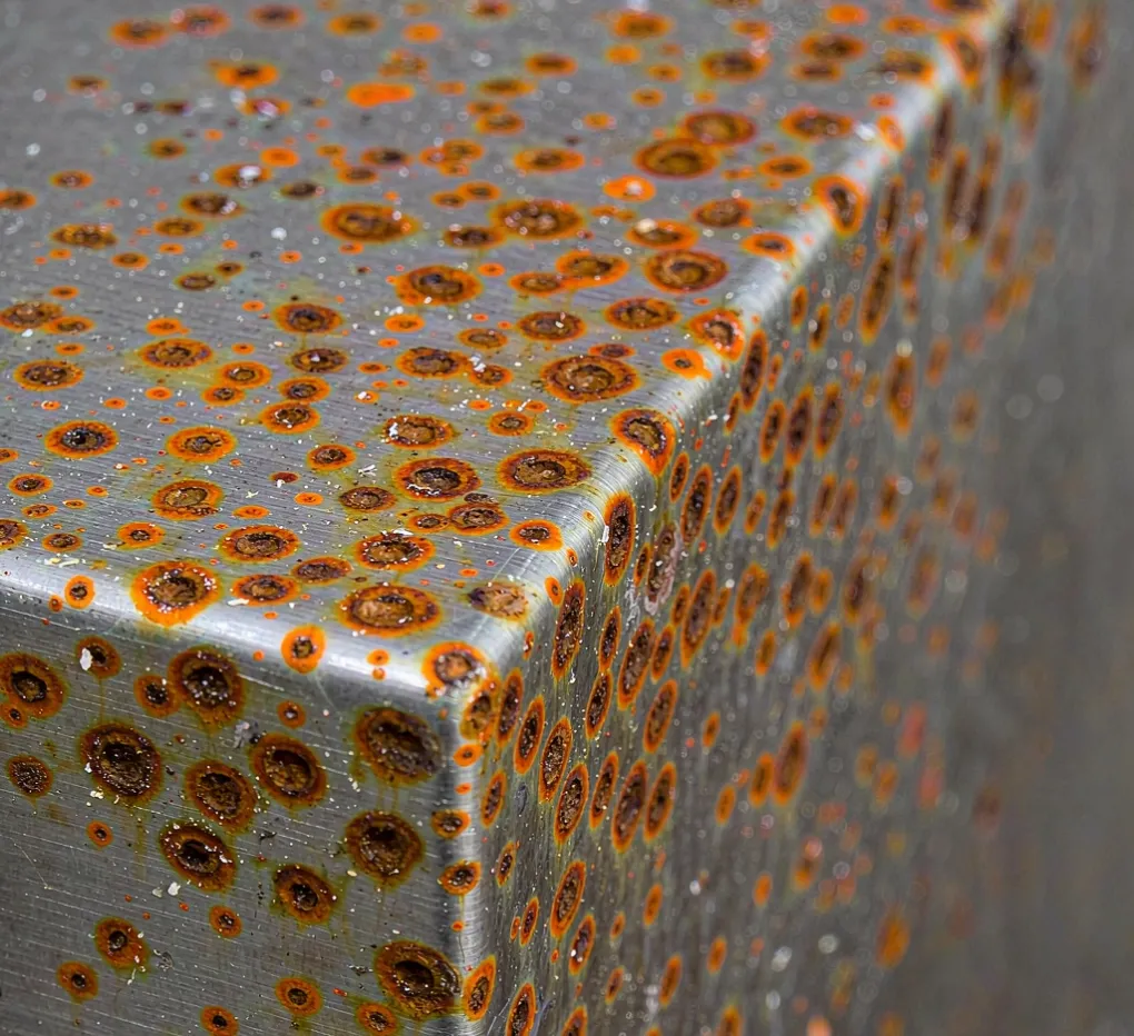
- The enclosure type and environment (drives material—carbon steel, 304, or 316 stainless—and cooling).
We review the drawing and BOM, size the backbone to the tighter of ampacity/rise/strength, and verify the assembly against the rating before shipment — with factory acceptance test records included.
FAQ
Q: Can I size the busbar by the total of all branch breakers?
No. Breakers aren't all at full load at once, so the bar carries the realistic demand plus margin, not the arithmetic sum of ratings. But it must still meet the temperature-rise and fault-withstand limits regardless of load diversity.
Q: Does a higher-ampacity breaker make the panel safer?
Only if the backbone and wiring behind it are rated for it. A 65 kA breaker on a 25 kA busbar doesn't raise the panel's SCCR—the bar caps it. Match the device to the backbone.
Q: Why no aluminum busbar?
Joint reliability and long-term torque retention. On a safety-critical spine we default to copper or tinned copper; the small material saving isn't worth a loose, overheating joint years later.
Q: How do I know the busbar was sized correctly after delivery?
Ask for the SCCR label, the busbar ampacity and temperature-rise data, and the as-built single-line diagram. A panel that can't show those was sized by guess.
Q: Does the enclosure material affect the busbar design?
Indirectly. A 316 stainless coastal panel still needs the same electrical sizing, but the layout must account for cooling and corrosion—tinned copper and sealed joints, not bare copper in a salt-air box.
Q: What's the lead time if I change the backbone after the drawing is approved?
Complete custom panels are built from one unit after drawing and BOM review, typically 35–40 days. Changing the distribution backbone late usually means re-reviewing the whole layout, so confirm the fault level and load list up front.
Engineering Takeaway
Size the busbar to the tightest of three constraints—continuous ampacity, temperature rise, and short-circuit withstand—not to amps alone. Tap each branch legally with its own protection and coordinate it so a fault drops one circuit, not the panel. Lay the backbone out first and give it bending space. And remember the bar sets the SCCR ceiling: a big breaker can't raise a panel past what the backbone can survive.
Get Your Panel's Power Distribution Specified Right
Send us the incoming supply, the available fault current at the panel, and your full load list with branch ampacities — plus the drawings and BOM — and we will size the backbone, verify the SCCR, and source the build. We reply within one business day.
- Email: info@uniregal.com
- Submit requirements: Upload your drawing for engineering review · Contact form
Lead times: complete custom panel from 1 unit (drawing + BOM review, 35–40 days); empty enclosure or shell MOQ 5, about 15 days; in-stock components ship in 3–5 days.