
Oct 12, 2026Control Panels
Control Panel Wiring and Labeling: A Practical Buyer's Checklist
What correct control panel wiring and labeling actually look like: wire color codes, terminal marking, cable tags, and the mistakes that cause startup delays. A field checklist for buyers.
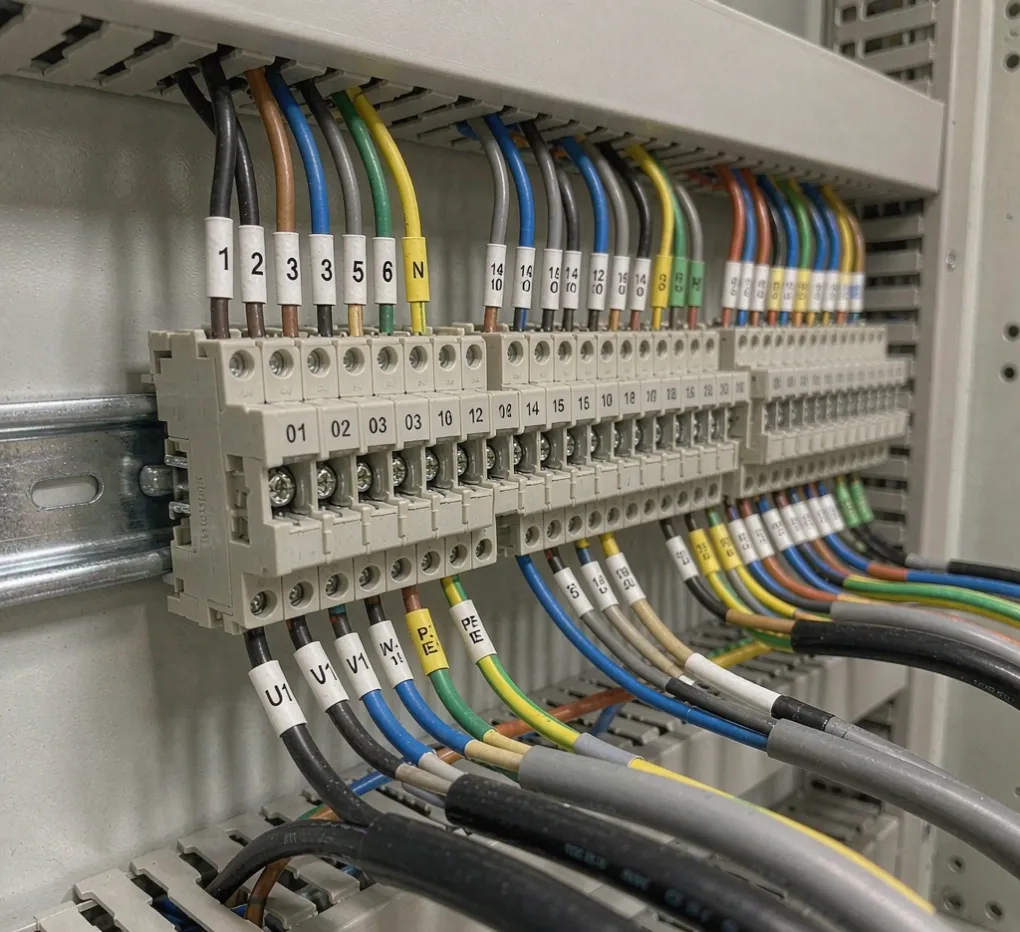
The panel powers up on the bench, the indicator lights all work, and the build looks tidy. Then it reaches site, gets bolted into the skid, and nobody can tell which terminal feeds the level transmitter or why the protective earth is daisy-chained through three devices. A neat panel is not the same as a correctly wired and labeled one — and the gap shows up at commissioning, not at acceptance.
This short guide gives you the checkpoints to write into a specification and to verify on delivery, so the panel your electrician opens is one they can actually work on.
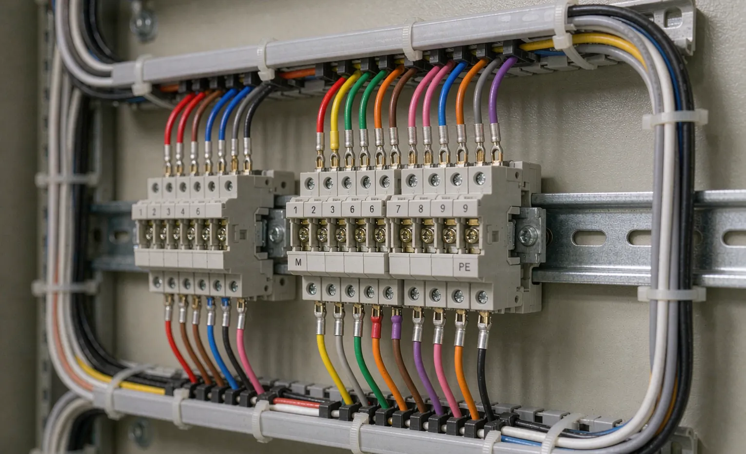
Wire color codes: know which standard you are buying
Wire colors are not universal, and assuming they are is a common source of confusion between a European-built panel and a North American one.
- IEC practice (IEC 60204-1): protective earth is green-and-yellow; AC phase conductors are brown/black/grey; neutral is blue; DC positive and negative follow a separate convention. Reference: IEC 60204-1.
- North American practice (NFPA 79 / UL 508A): grounded conductor is white or grey, equipment ground is green or bare, and ungrounded conductors are any color except those. Reference: UL 508A.
- DC control circuits: keep a consistent scheme — for example, 24 VDC positive in one color, negative in another, across the whole panel.
Buyer Decision: Name the color standard in the RFQ. A panel built to IEC colors shipped to a site expecting UL colors will pass a visual check and still confuse every electrician who opens it.
Terminal blocks: every point numbered and cross-referenced
A terminal block with no number is a guess. Require that: - Every terminal carries a permanent number matching the electrical schematic. - The schematic and the physical block use the same numbering — no "T1 on paper, terminal 14 in the box." - Bridge and jumper positions follow the drawing, not the assembler's habit. - Power and control terminals are grouped and separated so a mistake cannot bridge a 230 VAC circuit into a 24 VDC one.
When the numbering on the block and the drawing disagree, commissioning stops until someone traces every wire by hand. That is a day lost to a labeling error that costs nothing to prevent.
Cable and core marking: tag both ends
A wire is only identifiable if it is tagged where it enters and where it leaves. Require: - Each core marked with its destination terminal or function, readable without unplugging it. - External cables labeled at both the panel end and the field-device end. - A consistent tag format — "14LIT-01" meaning tank 14, level transmitter, point 01 — rather than "blue wire."
Field devices are often installed weeks after the panel. The cable that arrives unmarked becomes a discovery project. Marked cables let the site team land them without a call back to the builder.
Earthing and isolation you can see
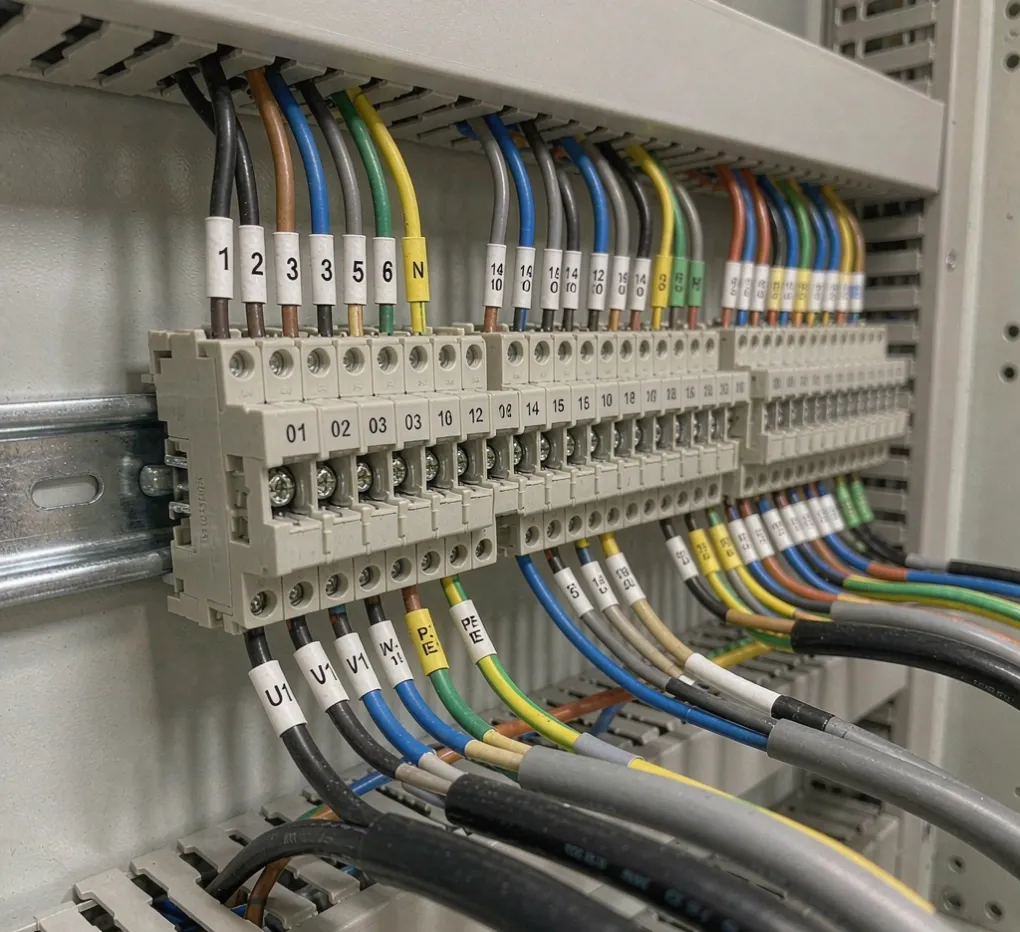
Protective earth is the one circuit that must never be subtle: - The earth conductor must be continuous and obviously green/yellow, not borrowed through a neutral. - Shielded cables should have their screen drained to earth at a defined point, not left floating and not grounded at both ends (which creates a ground loop). - Isolation between AC power, DC control, and analog signal circuits should be visible in both the layout and the schematic.
Most random, intermittent faults we are asked to diagnose trace back to an earth that looked connected but was bridged, looped, or shared with a neutral. Make the earth obvious and documented.
Mistakes that cause startup delays
The patterns below appear often enough that we wrote a full guide on hidden wiring problems that cause startup delays in OEM projects. In short form: - Terminals numbered on the drawing but not on the block. - Mixed color standards in one panel. - Shield drains left unconnected or double-grounded. - No cross-reference between the I/O schedule and the physical layout. - Earth and neutral interchanged under time pressure at the end of a build.
None of these fail a bench power-up. All of them fail a live startup.
A quick delivery checklist
Check | Pass criteria |
|---|---|
Wire colors | Match the named standard (IEC or UL/NFPA) |
Terminal numbers | Present on block, match schematic |
Cable tags | Both ends, consistent format |
Earth | Continuous, separated from neutral, visible |
Shields | Drained at one defined point |
Frequently asked questions
Do wire colors really matter if the panel works? Yes. A panel that works on the bench but uses the wrong color standard will confuse the electrician who services it at 2 a.m. during a fault. Colors are the shared language of the next person who opens the box.
Why must terminals be numbered if the drawing exists? Because the drawing is not in the panel. The number on the block is what the field electrician reads. If it disagrees with the drawing, every check becomes a manual trace, and startup slips.
Should I specify IEC or UL color codes? Match your destination and installed base. European and many export projects use IEC 60204-1; North American projects use UL 508A / NFPA 79. Name it explicitly so the builder does not default to their own habit.
What is the most common labeling mistake? Cables marked only at the panel end. By the time they reach the field device weeks later, the mark is gone or meaningless. Tag both ends with a consistent identifier.
Can poor labeling really delay startup? It is one of the most frequent causes. A panel with unnumbered terminals and untagged cables can take a full extra day of tracing before a single device is confirmed — time that comes out of your commissioning window.
Engineering Takeaway
Correct wiring and labeling are not cosmetics; they are what make a panel serviceable and a startup predictable. Name the color standard, number every terminal against the drawing, tag every cable at both ends, and keep the earth unmistakable. Write those four lines into the RFQ and you remove most of the wiring-driven startup delays before the panel is built.
For the full build and document expectations, see our control panel documentation checklist and what a custom control panel build involves.
Related guides
Request a wiring-standard review
If you have a panel on order and want a second check on the wiring and labeling specification before it is built, send the drawing and I/O schedule. We will flag the standard mismatches and missing cross-references that usually surface at startup. Submit your requirements and we will review it against your destination standard.
Need help specifying or sourcing this for your project? Request a quote - we reply within 1-2 working days with a technical review.