
Aug 17, 2026Integration & Compatibility
Hidden Wiring Problems That Cause Startup Delays in OEM Projects
OEM startup delays often come from wiring, not PLC logic. Learn how labeling, grounding, terminals, cable glands, and as-built checks prevent costly commissioning delays.
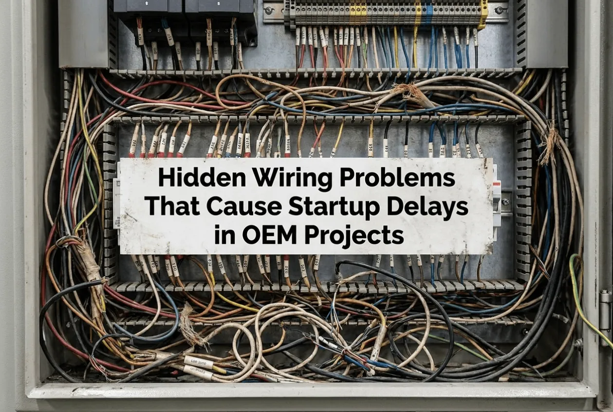
Hidden Wiring Problems That Cause Startup Delays in OEM Projects
In many OEM projects, the control panel arrives on site looking finished. The PLC program has been loaded, the HMI powers up, the VFDs communicate, and the FAT record shows no major issue.
Then startup begins, and the project loses hours—or days—on something much smaller.
A field cable lands on the wrong terminal. An analog signal becomes unstable when a motor starts. A cable gland does not match the actual cable diameter. A last-minute wiring change was never updated on the drawing, so the commissioning engineer is troubleshooting a panel that no longer matches the documentation.
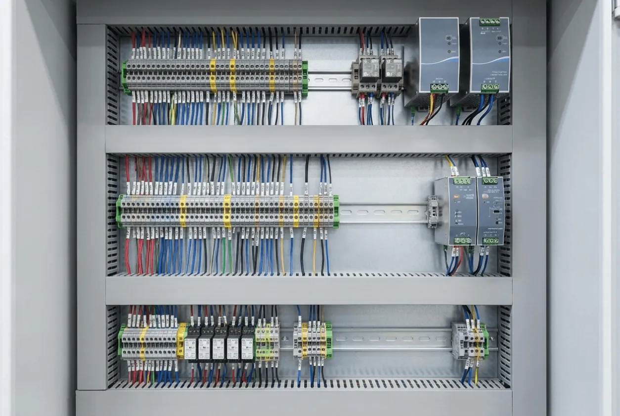
These failures are rarely expensive to prevent during panel assembly. They become expensive when they are discovered after the OEM control panel has been shipped, installed, and connected to the machine.
For buyers sourcing custom control panels, PLC control panels, or VFD control panels, wiring quality should therefore be reviewed as part of startup risk, not simply as a workmanship issue.
The real question is
What wiring problems should an OEM buyer verify before a control panel leaves the factory?
Quick Decision Matrix: Where Startup Wiring Problems Usually Come From
Wiring Risk | What Happens at Startup | What the Buyer Should Require Before Shipment |
|---|---|---|
Wrong or missing wire labels | Technicians trace circuits manually or connect the wrong field device. | Point-to-point verification against the final schematic |
Poor grounding or shielding | Analog signals drift, communication becomes unstable, and VFD-related faults appear. | Grounding and shield review based on the actual control architecture |
Incorrect terminals or cable glands | Loose power connections, damaged cables, or water ingress | Torque records, cable-size confirmation, and gland schedule |
As-built drawing mismatch | The commissioning team troubleshoots against obsolete information. | Final as-built drawings verified against the physical panel |
Crowded power and signal wiring | Noise and difficult fault tracing | Separation reviewed during panel layout and wiring inspection |
The important point is that these are interface problems.
The panel may work correctly by itself. The fault appears when the electrical control cabinet is connected to the real machine, field instruments, and power system.
1. The Wrong Wire Label Can Make a Correct Panel Look Faulty
Wire labeling sounds basic, which is exactly why it is often underestimated.
During workshop testing, technicians normally work from known I/O points. A simulated limit switch may be connected directly to the expected PLC input, so the program behaves correctly.
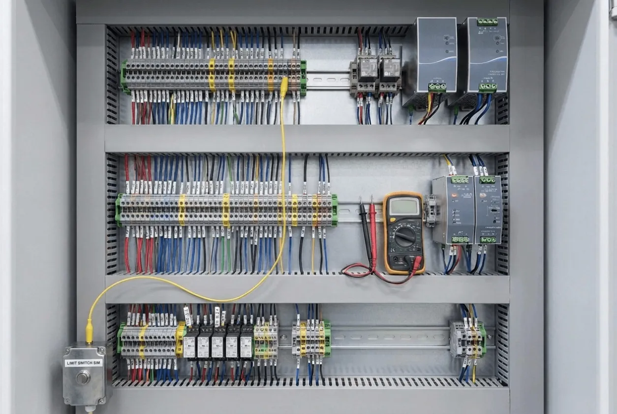
At the site, the commissioning engineer does not have that controlled environment. He may have hundreds of cables coming from motors, sensors, valves, and junction boxes. The wire marker is supposed to tell him exactly where each conductor belongs.
If the marker is wrong, a correct schematic and a correct PLC program can still produce the wrong field result.
The problem becomes particularly expensive on OEM equipment because the panel builder and the machine builder may be different companies. Once the machine is assembled in another country, the commissioning team has to determine whether the problem comes from the PLC software, field wiring, machine device, or control panel.
For a custom OEM control panel, the pre-shipment inspection should therefore verify wire numbers against the final electrical schematic rather than simply checking whether labels look neat.
A printed marker is not evidence of correct wiring.
It is only useful when the marker, terminal, and drawing all describe the same circuit.
2. Grounding and Shielding Problems Often Wait Until the Machine Is Running
Some wiring faults are easy to see.
Noise-related problems are not.
A 4–20 mA signal may remain stable during FAT and begin drifting when several motors are running. A communication network may work normally until a large contactor switches. A VFD may create interference that appears as an unstable sensor reading rather than a drive fault.
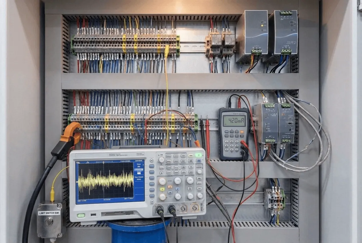
This is why grounding and shielding should be treated as part of the control panel engineering, not left to general workmanship.
The correct shielding arrangement depends on the signal type, equipment manufacturer, grounding architecture, and installation. There is no useful universal rule that every shield should simply be connected at one end in every application.
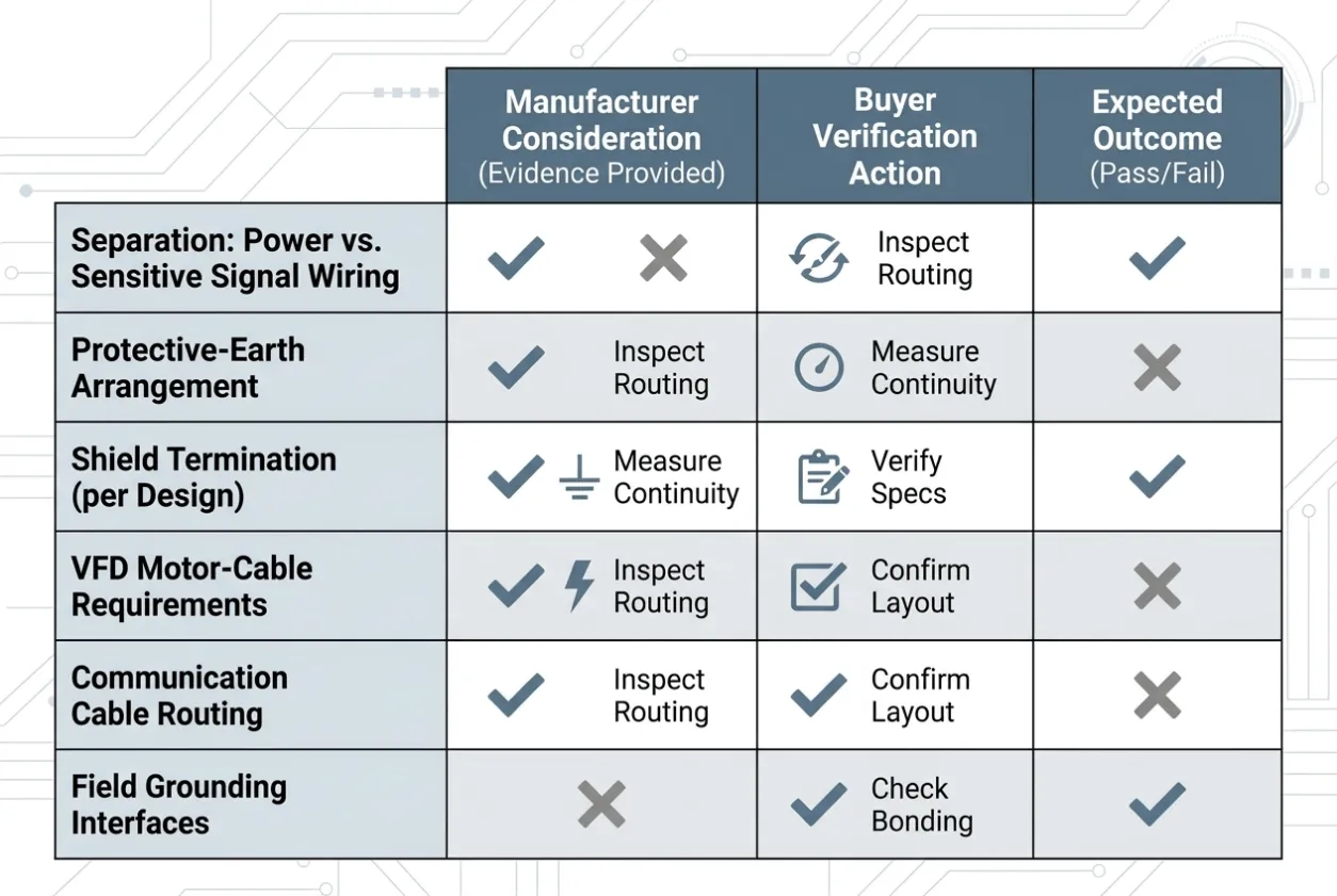
What the buyer should expect from a competent industrial control panel manufacturer is evidence that the panel builder has considered:
- separation between power and sensitive signal wiring;
- the protective-earth arrangement;
- shield termination according to the instrument and system design;
- VFD motor-cable requirements;
- communication cable routing;
- field grounding interfaces.
This becomes especially important for VFD control panels, process instrumentation panels, and machine automation systems where low-level signals share an enclosure with switching devices and motor circuits.
A clean-looking wiring duct does not tell you whether the EMC strategy is correct.
3. Terminals and Cable Glands Become Site Problems When They Are Treated as Accessories
A loose power terminal may operate normally during a short factory test.
After repeated heating and cooling cycles, the connection can become unstable. What initially looks like an intermittent VFD or motor problem may eventually be traced to one termination.
The same principle applies to cable glands.
During quotation, glands often appear as a minor line item. During installation, they determine whether the cable is properly retained and whether the enclosure maintains the environmental protection the project requires.
If the field cable is larger than assumed, installers sometimes replace the gland on-site, enlarge the opening, or improvise a new entry. That can compromise an otherwise well-designed IP-rated control cabinet.
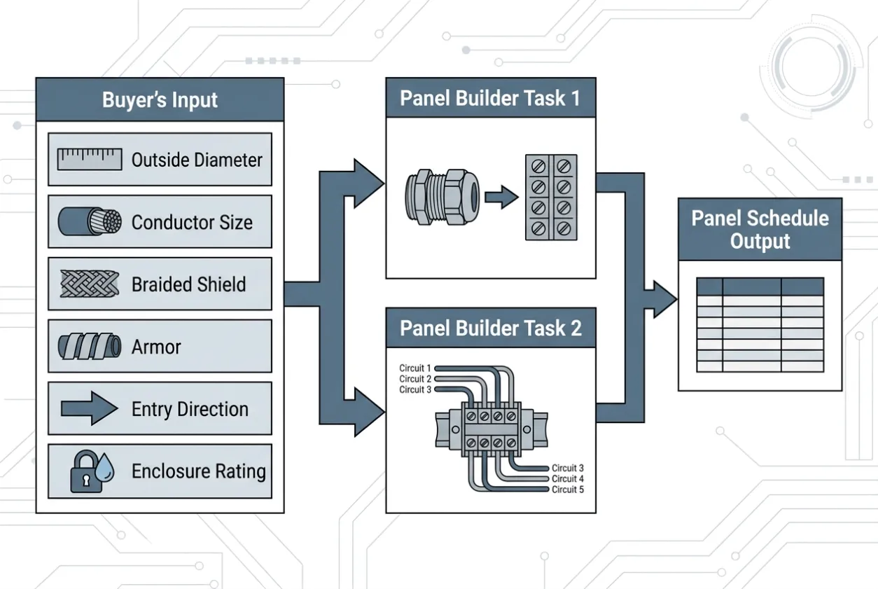
For OEM projects, buyers should therefore provide cable information early enough for the panel builder to prepare the correct gland and terminal schedule.
That should include the actual:
- cable outside diameter;
- conductor size;
- shield requirement;
- armor requirement where applicable;
- cable-entry direction;
- required enclosure rating.
Power-terminal torque should also be verified according to the applicable component requirements before shipment.
These details are inexpensive while the electrical control cabinet is still on the assembly bench. Once the panel is installed inside a machine or production line, access may become much more difficult.
4. The Most Dangerous Drawing Is the One That Was Correct Last Week
OEM projects change.
A proximity sensor is replaced. The machine builder adds another interlock. A terminal block moves because cable routing changed. The customer asks for one additional safety signal three days before shipment.
None of that is unusual.
The problem begins when the physical control panel changes and the documentation does not.
At startup, the commissioning engineer assumes that terminal X12:14 goes to one device because that is what the drawing says. The panel, however, was modified during final assembly.
The engineer spends the next hour proving that the circuit does not behave according to the drawing before somebody discovers the undocumented change.
This is as-built drift, and it is one of the easiest ways to turn a small workshop modification into an international commissioning problem.
For a custom control panel, the drawing package packed with the shipment should represent the panel that actually left the factory.
Not the design that was originally approved.
Not the revision used during the first FAT.
The final built panel.
Example: The Machine Would Not Enter Automatic Mode
On one representative OEM machine project, the control panel passed its workshop functional test and was shipped with the equipment.
During site commissioning, manual operation worked correctly, but the machine would not enter automatic mode. The PLC showed that one safety-related permissive was missing.
The commissioning team initially focused on software because the corresponding field device appeared to operate normally.
The I/O was checked again. The PLC logic was reviewed. The field technician then traced the cable from the machine back to the panel.
That was when the issue became clear.
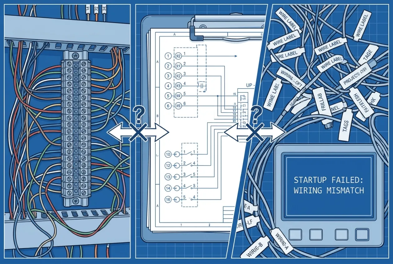
A late-stage wiring modification had moved the field signal to a different terminal, but the final drawing still showed the original terminal number. The wire marker had also been copied from the earlier drawing revision.
Electrically, the panel was not seriously defective.
The machine lost startup time because the physical wiring, wire identification, and as-built documentation no longer agreed with one another.
The correction itself took minutes once the fault was located.
Finding it took much longer.
After that review, the pre-shipment process was changed so that final I/O verification was performed against the physical panel and the released as-built schematic together before the cabinet was packed.
That is the kind of control that matters in OEM work.
What OEM Buyers Should Require From a Control Panel Supplier
If startup time matters, do not ask only whether the panel has passed FAT.
Ask what was actually verified.
For a custom control panel manufacturer or OEM panel supplier, a useful pre-shipment scope should include:
Verification | Why It Matters |
|---|---|
Point-to-point wiring check | Confirms the physical circuit matches the schematic |
Wire-label verification | Reduces site tracing and incorrect connections |
Terminal torque verification | Reduces power-connection problems after shipment |
Grounding and shielding review | Reduces noise and communication problems |
Cable gland schedule | Confirms the enclosure matches actual field cables |
I/O test | Confirms PLC signals reach the correct terminals |
Alarm and interlock test | Verifies control behavior before the machine reaches the site |
As-built drawing review | Gives commissioning engineers documentation they can trust |
This is also where the commercial difference between panel suppliers becomes clearer.
Two quotations may contain the same PLC, HMI, breakers, and enclosure. One supplier may be pricing component assembly. Another may also include the verification required to make site integration more predictable.
Those are not necessarily equivalent OEM control panel quotations.
The Buyer Risk Is Usually at the Interface
OEM panels are especially sensitive to wiring quality because the control cabinet rarely operates as an independent product.
It has to connect with somebody else’s machine.
That interface may include:
- field motors;
- solenoid valves;
- encoders;
- safety switches;
- analog instruments;
- remote I/O;
- Ethernet or fieldbus networks;
- customer power supplies.
This is where small assumptions become commissioning problems.
If the panel builder does not know the actual cable size, gland selection becomes an assumption. If field-device information changes without reaching the panel shop, terminal assignments can become obsolete. If the machine builder and panel builder use different grounding assumptions, the issue may not appear until power is applied to the complete machine.
For buyers, this is one reason to select a control panel supplier based on engineering coordination and FAT discipline rather than BOM price alone.
Common Mistakes
❌ Approving the panel because the PLC and HMI worked during FAT without checking the field wiring interfaces.
❌ Checking wire labels visually without verifying them against the final schematic.
❌ Treating grounding and shielding as a standard workshop habit instead of part of the project design.
❌ Ordering cable glands before actual field cable diameters are confirmed.
❌ Allowing last-minute wiring changes without updating the as-built drawings.
❌ Comparing custom control panel manufacturers only by component brands and cabinet price while ignoring wiring inspection and pre-shipment verification.
Engineering Takeaway
Most wiring-related startup delays are not caused by complicated engineering failures.
They happen because a small difference between the drawing, physical panel, and field installation survives all the way to the site.
For OEM buyers, the best time to find that difference is while the control cabinet is still open on the workshop bench.
A reliable pre-shipment process should verify the wiring, labels, grounding, cable interfaces, and as-built documentation as one system. When those items are correct before crating, the commissioning team can spend its time starting the machine instead of tracing wires.
Sourcing an OEM Control Panel?
If you are comparing OEM control panel manufacturers, custom control panel suppliers, or electrical control cabinet manufacturers in China, do not send only a BOM and ask for the lowest price.
Send UniRegal your electrical schematic, I/O list, equipment layout, field cable information, and panel specification.
We can review the enclosure, PLC/HMI/VFD components, wiring interfaces, FAT requirements, and pre-shipment documentation together, then match the project with a suitable panel-building source in our Foshan supply network.
For OEM projects, the goal is not simply to ship a completed cabinet.
It is to ship a control panel that your commissioning team can connect, verify, and start without discovering basic wiring problems thousands of kilometers from the workshop.
Send Your OEM Control Panel Drawing for a Technical and Commercial Review