MCC Panels
MCC Panel Supplier for Motor Control Centers
MCC panels and motor control centers for pumps, fans and conveyors — complete wired panels from 1 unit, empty enclosures from 5, with FAT and as-built drawings.
Specifications
- Application
- Custom Industrial Automation
- Control Method
- PLC / Relay Based
- Voltage
- 220V / 380V / 480V Available
- Protection Rating
- IP54 / IP65 Optional
- Communication Protocol
- Modbus / Profinet / Ethernet/IP
- Testing
- FAT Before Shipment
- Customization
- Available
Quick Answer
A motor control center groups multiple motor feeders - starters, VFDs, soft-starters - in one structured enclosure. UniRegal builds MCCs to your motor list and starting methods using approved brands, with clear tagging to drawings. ~15-day lead time; UL 845 routed per project. Provide the motor schedule for quotation.
MCC Panels for Centralized Multi-Motor Control and Maintenance
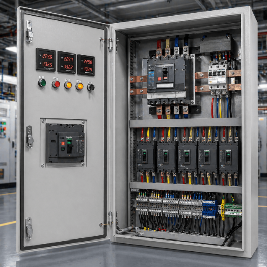
UniRegal supplies custom MCC Panels for industrial facilities, water treatment plants, pump stations, HVAC systems, production lines and process operations where multiple motors must be controlled from one organized electrical assembly.
An MCC should not be selected only by the number of motors or cabinet dimensions. The correct architecture depends on how much of the process may stop during a feeder fault, how quickly a failed unit must be replaced, whether future motors will be added and how motor data will be integrated with the plant control system.
For the buyer, the real value of an MCC is not that it can start several motors. It is that each motor feeder can be identified, protected, isolated, maintained and expanded without turning every intervention into a plant-wide electrical problem.
Send us your motor list and single-line diagram for MCC architecture review.
When Does a Project Need an MCC?
An MCC becomes useful when the project requires more than basic motor starting.
Typical reasons include:
- Multiple motors share one electrical supply.
- Motor feeders must be grouped by process or plant area.
- Individual feeder isolation is required.
- Maintenance downtime affects production.
- Starter and protection designs need standardization.
- Spare feeders or future motor additions are expected.
- The PLC, SCADA or DCS needs motor status and diagnostic data.
- Cable routing and field termination must be organized centrally.
- The plant requires clear feeder identification and documentation.
There is no universal motor quantity at which an MCC becomes mandatory. A project with several critical motors may justify an MCC because of maintenance and isolation requirements, while a simple skid with more motors may still use an integrated machinery control panel.
The decision should follow the operating and maintenance strategy rather than a fixed motor count.
Buyer Decision Information: Fixed, Plug-In, Withdrawable or Intelligent MCC?
The most important MCC purchasing decision is often the structure of the motor feeder units.
MCC Architecture | Best-Fit Situation | Main Advantage | Buyer Must Confirm |
|---|---|---|---|
Fixed MCC | Stable motor configuration with infrequent feeder replacement | Simpler construction and lower initial cost | Required shutdown and access for maintenance |
Plug-In MCC | Projects requiring modular feeder organization | Easier feeder installation and future modification | Unit compatibility, isolation method and spare-unit strategy |
Withdrawable MCC | Operations where feeder replacement time affects production | A unit can be isolated and removed according to the approved operating procedure | Connected, test, isolated and withdrawn positions |
Intelligent MCC | Plants requiring motor data, diagnostics and remote integration | Centralized monitoring and faster fault identification | Data points, protocol, network architecture and system ownership |
Hybrid MCC | Projects with different criticality levels across motor feeders | Uses fixed, withdrawable and intelligent feeders where each is justified | Which feeders require each architecture |
A withdrawable design is not automatically the best answer for every motor. It adds cost, mechanical complexity and space requirements, so it should be used where reduced maintenance time or feeder replacement flexibility has measurable operational value.
Design the MCC Around the First Failure, Not Only the First Start-Up
Many MCCs appear successful during commissioning because every motor starts and stops as expected. The real design quality becomes visible later, when one feeder trips during production and the maintenance team must identify, isolate and repair it.
Before approving the MCC layout, the buyer should ask:
- Can the failed motor feeder be identified immediately?
- What must be de-energized before the feeder can be inspected?
- Can adjacent feeders remain available?
- Is there enough access to test or replace components?
- Are the power and control terminals clearly separated?
- Can an installed spare unit replace a critical feeder?
- Will the maintenance team have the latest drawings and settings?
- Does the process require a bypass or standby motor strategy?
- Can future feeders be added without rebuilding the main bus system?
These questions define the practical shutdown boundary of the MCC. They are more useful than judging the panel only by external appearance.
MCC Panel vs Motor Control Panel, PLC Panel and MDB
Product | Primary Responsibility | Main Design Question |
|---|---|---|
MCC Panel | Centralized control and protection of multiple motor feeders | How should motors be grouped, isolated, maintained and expanded? |
Motor Control Panel | Control of one motor or a small motor group | How should this motor start, run, reverse or change speed? |
PLC Control Panel | Automation logic, I/O, sequence and communication | How should the process be controlled? |
Main Distribution Board | Main low-voltage power receiving and distribution | How should power be distributed to major downstream systems? |
An MDB or PCC may supply power to the MCC. The MCC then distributes that power to individual motor feeders, while a separate PLC Panel may manage process sequences and interlocks.
These functions can be integrated when required, but the quotation and drawings should define the responsibility of each section clearly.
The Motor List Is the Foundation of the MCC
An accurate MCC cannot be developed from a total motor quantity alone.
Each feeder should be defined in the motor list or feeder schedule with information such as:
Motor List Field | Why It Matters |
|---|---|
Motor Tag | Links the feeder to drawings and field equipment |
Equipment Description | Identifies the pump, fan, conveyor or process load |
Motor kW or HP | Provides the basic power rating |
Full-Load Current | Supports starter and protection selection |
Voltage and Frequency | Defines the electrical supply |
Starting Method | Defines the feeder architecture |
Duty and Starts per Hour | Affects starter rating and thermal performance |
Local or Remote Control | Defines control devices and external interfaces |
Process Permissives | Defines the conditions required before starting |
Run, Trip and Available Signals | Defines PLC, DCS or SCADA integration |
Cable Size and Entry | Affects terminal and cable-compartment design |
Criticality | Helps decide fixed, withdrawable, spare or redundant design |
DOL, reversing, star-delta, soft-starter and VFD feeders can all be included in an MCC. Detailed selection of these starting methods belongs to the motor-specific engineering review; the MCC decision is how these feeders should be organized and maintained as one system.
Feeder Standardization and Spare Strategy
A spare compartment is not the same as a spare motor feeder.
Spare Space
Spare space reserves physical room for a future feeder, but the future installation may still require bus connections, wiring, terminals, doors and engineering changes.
Prepared Spare Compartment
A prepared compartment may include part of the bus, control and mechanical infrastructure needed for a future unit. The exact preparation scope must be shown in the quotation.
Installed Spare Feeder
An installed spare feeder is supplied with the required starter, protection, wiring and terminals. It may be reassigned to a compatible motor according to the approved design.
Spare Withdrawable Unit
For withdrawable MCCs, a separate spare unit may reduce replacement time when critical feeders use standardized sizes and interfaces.
The buyer should not request an undefined percentage of “spare capacity.” The project must distinguish among spare busbar current, empty compartments, prepared compartments, installed spare feeders and loose spare units.
Fixed vs Withdrawable MCC: Lifecycle Decision
Decision Factor | Fixed MCC | Withdrawable MCC |
|---|---|---|
Initial Cost | Generally lower | Generally higher |
Mechanical Complexity | Lower | Higher |
Feeder Replacement | Requires more internal work | Designed for unit removal according to procedure |
Standardization | Component-level | Unit and component-level |
Shutdown Planning | Usually more dependent on access and isolation | May reduce the affected maintenance area |
Spare Strategy | Spare components or fixed feeders | Spare components, compartments or complete units |
Best Fit | Stable systems with planned maintenance windows | Critical processes where feeder replacement time matters |
Withdrawable construction does not automatically permit live work or hot swapping. The permitted operating sequence depends on the tested assembly design, unit position, interlocking, manufacturer instructions, risk assessment and site safety procedure.
Internal Separation and Maintenance Access
The form of internal separation affects how busbars, functional units, terminals and cable compartments are divided inside an MCC.
The required arrangement should consider:
- Access to motor feeders
- Separation of main and vertical busbars
- Power and control wiring segregation
- Field-cable termination
- Maintenance while adjacent sections remain in service
- Protection against accidental contact
- Fault containment expectations
- Front or rear access
- Top or bottom cable entry
A higher form of separation may improve compartmentalization, but it does not make energized work automatically safe. Isolation, verification of absence of voltage, lockout procedures and the project’s electrical-safety requirements still apply.
The terms “arc-resistant,” “arc-proof” or “internal arc classified” should only be used when the complete assembly has the required design verification and supporting test evidence.
Intelligent MCC: Decide the Data Before Choosing the Protocol
An Intelligent Motor Control Center uses networked protection devices, smart motor controllers, VFDs or communication modules to provide motor information to a PLC, SCADA, DCS or facility system.
Available data may include:
- Run and stop status
- Available and not-available status
- Trip cause
- Motor current
- Thermal loading
- Start count
- Running hours
- Phase condition
- VFD speed and frequency
- Alarm history
- Energy data where supported
- Maintenance indicators
The communication protocol should not be selected before defining what information is actually required and where it will be used.
The technical review should confirm:
- Required data points
- Control commands permitted over the network
- Hardwired emergency and safety signals
- Network topology
- Communication protocol
- Device addresses
- PLC, DCS or SCADA ownership
- Loss-of-communication behaviour
- Local operating capability
- Backup of device settings
- Cybersecurity requirements where applicable
Adding a communication module to every feeder does not automatically make the MCC useful. The value comes from making the data available, understandable and actionable for operations and maintenance.
VFD MCC Thermal and EMC Planning
An MCC containing several VFD feeders creates a different design problem from an MCC containing mainly contactor starters.
The combined drive heat load, not only the rating of one VFD, must be reviewed.
The design may need to consider:
- Total VFD heat dissipation
- Simultaneous motor loading
- Ambient temperature
- Ventilation or cooling method
- Drive spacing and manufacturer clearances
- Enclosure protection rating
- Clean and dirty airflow paths
- Control and communication cable routing
- Motor cable shielding
- Grounding and bonding
- Line reactors, EMC filters or harmonic mitigation
- Output reactors or filters for long motor cables
- Bypass and isolation requirements
- Access for filter cleaning and fan replacement
Installing several drives in a sealed high-IP enclosure without a thermal calculation can create an MCC that passes factory inspection but overheats after full plant loading.
Protection and Fault Isolation
Each motor feeder requires a defined protection arrangement based on the motor, cable, starter and operating duty.
The engineering review may include:
- Short-circuit protection
- Motor overload protection
- Phase-loss or phase-unbalance protection
- Earth-fault protection where required
- Locked-rotor or stall protection
- Underload protection for relevant applications
- Temperature inputs where provided
- Breaker, fuse, contactor and overload coordination
- Upstream and downstream selectivity
- Alarm and trip indication
- Restart behaviour after power loss
- Local and remote emergency-stop interfaces
The fault level must be confirmed for the complete MCC assembly. It should not be inferred from the interrupting rating printed on one feeder breaker.
What Buyers Should Compare Between MCC Quotations
Comparison Point | Why It Matters |
|---|---|
Fixed, Plug-In or Withdrawable Construction | Determines maintenance method and replacement strategy |
Feeder Schedule | Confirms every motor is included correctly |
Unit Size and Interchangeability | Affects standardization and spare-unit use |
Busbar Rating and Fault Withstand | Determines system capacity and fault performance |
Feeder Protection Coordination | Affects motor, cable and starter protection |
Internal Separation | Affects access and compartmentalization |
Cable Compartment | Determines whether field termination is practical |
VFD Thermal Design | Prevents overheating under simultaneous loading |
Communication Scope | Defines usable motor data and system integration |
Spare Capacity | Must distinguish space, prepared feeders and installed spares |
Component Models | Affects replacement availability and lifecycle support |
FAT Scope | Defines which feeder functions are actually verified |
Documentation | Supports commissioning, troubleshooting and future expansion |
Assembly Verification | Supports the claimed standard and performance |
A lower quotation may exclude prepared spare compartments, withdrawable units, communication devices, thermal management, detailed FAT or as-built documentation. These omissions are not always visible in the cabinet dimensions.
Technical Configuration Options
Parameter | Available Configuration |
|---|---|
Product | MCC Panel / Motor Control Center |
Application | Centralized Multi-Motor Control |
Voltage | 380V / 400V / 415V / 480V / 690V or project-specific |
Frequency | 50Hz / 60Hz |
Main Busbar | Copper or Aluminum |
Construction | Fixed / Plug-In / Withdrawable / Hybrid |
Motor Feeders | DOL / Reversing / Star-Delta / Soft Starter / VFD |
Control | Local / Remote / Automatic / PLC or DCS Command |
Communication | Hardwired / Modbus / PROFINET / EtherNet/IP / PROFIBUS |
Internal Separation | According to project and applicable assembly design |
Cable Entry | Top / Bottom / Front / Rear, subject to layout |
Installation | Indoor / Outdoor |
Enclosure | Floor-Standing, Modular and Project-Specific |
Protection Rating | Selected according to the site environment |
Metering | Main and Feeder Metering as required |
Expansion | Spare Bus Capacity / Space / Prepared or Installed Feeders |
Standards | Applicable IEC or Local Project Requirement |
Documentation | SLD, GA, Feeder Schedule, Schematics, BOM and FAT Records |
Final current ratings, fault withstand, enclosure protection, standards and construction are confirmed from the approved project data.
MCC Drawing and Documentation Package
Depending on the agreed scope, the documentation package may include:
- Single-line diagram
- General arrangement drawing
- MCC feeder schedule
- Motor list
- Main and vertical busbar ratings
- Power wiring diagrams
- Control schematics
- Terminal plans
- Cable-entry layout
- Bill of materials
- Protection-device schedule
- VFD or soft-starter parameter records
- Communication architecture
- Device address list
- Nameplate and label schedule
- FAT procedure and test report
- Spare-parts list
- Packing list
- As-built drawings
An MCC should not be approved from a front-view photograph. The motor list, feeder schedule, internal layout and control schematics determine whether it will work with the plant.
Factory Acceptance Testing
The FAT should verify the MCC feeder by feeder rather than treat the complete assembly as one general control panel.
Typical inspection and test items may include:
- Component model and rating verification
- Main and vertical busbar inspection
- Mechanical assembly and compartment checks
- Protective bonding and earth continuity
- Wiring continuity and terminal inspection
- Insulation-resistance testing
- Breaker and isolator operation
- Fixed, test and isolated unit-position checks where applicable
- Mechanical and electrical interlock verification
- Starter operation for each feeder type
- Overload and protection-signal simulation
- Local and remote control checks
- VFD or soft-starter command testing
- PLC, DCS or SCADA signal verification
- Communication and device-address checks
- Metering checks
- Label and drawing consistency review
- ATS or bus-coupler logic checks where included
- Final inspection before packing
Additional dielectric tests, secondary-injection tests, witnessed FAT or special acceptance requirements should be agreed before production.
What FAT Does Not Automatically Prove
When the actual motors, process instruments and mechanical loads are not available at the factory, FAT cannot fully prove:
- Motor rotation
- Acceleration under real load
- Final overload settings
- VFD tuning under process conditions
- Field cable integrity
- Plant network performance
- Site fault level
- Final protection selectivity
- Actual arc-flash incident energy
- Process sequence performance under all operating conditions
These items require approved project data and, where applicable, site commissioning.
Information Required for an MCC Quotation
Please provide the following information where available:
Required Information | Example |
|---|---|
Single-Line Diagram | Incoming supply, bus sections and outgoing feeders |
Motor List | Tag, kW/HP, voltage, FLA, duty and starting method |
Feeder Schedule | Starter type, breaker, cable and control requirement |
MCC Structure | Fixed, plug-in, withdrawable or evaluation required |
Main Bus Rating | Current and short-circuit withstand requirement |
Incoming Supply | Voltage, frequency, incomer and earthing system |
Control Philosophy | Local, remote, automatic and restart behaviour |
PLC/DCS Interface | Signals, protocol and network ownership |
Maintenance Strategy | Required isolation and replacement approach |
Spare Strategy | Spare space, prepared feeders or complete spare units |
Cable Entry | Top, bottom, front or rear |
Installation Environment | Indoor, outdoor, dust, heat, humidity or corrosion |
Enclosure Requirement | IP/NEMA rating and access limitations |
Preferred Components | Approved breaker, starter, VFD and protection brands |
Standards | Applicable IEC or local project requirement |
Documentation | Required drawings, test reports and approval stages |
Quantity and Destination | Number of assemblies and project location |
If the motor list is incomplete, send the preliminary single-line diagram, motor quantity, largest motor rating, process description and expected control architecture. These details allow the main clarification points to be identified before quotation.
Typical Applications
Custom MCC Panels can be configured for:
- Water and wastewater treatment plants
- Pumping stations
- HVAC central plants
- Manufacturing facilities
- Conveyor and material-handling systems
- Food and beverage production
- Chemical and process plants
- Mining and heavy industry
- Oil and gas utilities
- Infrastructure projects
- Power-generation auxiliary systems
- Industrial utility plants
The application name does not define the final MCC. Motor criticality, maintenance requirements, operating duty and control architecture determine the appropriate configuration.
Frequently Asked Questions
1. When should an MCC be used instead of separate motor control panels?
An MCC is normally considered when multiple motors require a common busbar, structured feeder organization, centralized maintenance or plant-level integration. The decision depends on operational complexity and maintenance strategy rather than a fixed motor quantity.
2. What is the difference between fixed and withdrawable MCC feeders?
Fixed feeders are wired and installed permanently within the assembly. Withdrawable units are designed to move through defined connected, test, isolated or withdrawn positions according to the assembly design, allowing more standardized removal and replacement.
3. Does a withdrawable MCC allow hot swapping?
Not automatically. Withdrawable construction does not by itself authorize unit removal while the MCC is energized. The permitted procedure depends on the tested assembly, interlocks, isolation position, manufacturer instructions, risk assessment and site electrical-safety rules.
4. What is the difference between spare space and a spare feeder?
Spare space reserves physical room. A prepared compartment includes agreed mechanical or electrical provisions, while an installed spare feeder contains the required protection and control equipment. These scopes should be priced and documented separately.
5. What makes an MCC intelligent?
An intelligent MCC uses networked protection and control devices to provide motor status, current, trip causes, running hours and other diagnostic data. Its value depends on how that data is integrated into PLC, SCADA, DCS or maintenance systems.
6. How is heat managed in a VFD MCC?
The design should calculate the combined heat losses of simultaneously operating drives and consider ambient temperature, spacing, enclosure protection, ventilation or cooling, cable routing and manufacturer derating requirements.
7. Does a higher form of separation make energized maintenance safe?
No. Internal separation may improve compartmentalization and access, but it does not replace isolation, lockout, voltage verification, PPE or an approved safety procedure. The claimed form must also be supported by the complete assembly design.
8. What is required for an accurate MCC quotation?
The most important documents are the single-line diagram, motor list and feeder schedule. The quotation also requires the bus rating, fault level, control philosophy, MCC structure, communication requirements, spare strategy, environment and applicable standards.
Start Your MCC Project
Send us your motor list, single-line diagram, feeder schedule, required MCC structure, control philosophy, fault level and communication requirements.
Sourcing MCC panels? We consolidate enclosures, breakers and drives from multiple Foshan suppliers into one build — single-point accountability. Talk to our team about your projectrequirements and expansion plan.
UniRegal will review how the motors should be grouped, isolated, maintained and integrated before defining the MCC configuration. This allows the quotation to reflect the plant’s operating and maintenance requirements rather than only the motor count and cabinet size.
Related Guides & Solution Centers
Planning an MCC? Request a quote
Real deliveries through our Foshan sourcing network. Client names withheld by request.
Project Example — 4-Section Motor Control Center, 2026
- Scope: 1× 4-section MCC for a water pump station — 4 pumps, VFD + soft-start, compartmented and withdrawable.
- Panel: Free-standing IP54 enclosure, VFD per pump with bypass, integral metering, door-mounted HMI.
- Country: Middle East.
Engineering Review Example
Customer Requirement: Four pumps that had to alternate duty and survive a VFD failure without taking the station offline.
Our Suggestion: One compartment per pump, VFD with a manual bypass contactor, and a rotation relay so duty alternates automatically.
Final Design: 4-compartment MCC, VFD + bypass per section, door HMI showing run hours, FAT run-test of each section under load before shipment.
Why Choose UniRegal for MCC Panels
- Foshan multi-supplier sourcing — enclosure + VFD + protection devices sourced together, one build.
- Prototype & project orders from 1 unit; lead time confirmed after drawing & BOM review; VFD / soft-start / components ship in 3–5 days.
- UL 845 routed per project — matched to a UL-listed fabricator, build to print.
- Compartmented & serviceable — we build per-section so one fault doesn't stop the line.
- FAT before shipment — each section run-tested, inspection photos on request.
Lead Time & FAT
Item | Lead time |
|---|---|
Enclosure / MCC structure | ~15 days |
VFD / soft-start / components | 3–5 days |
FAT + inspection | Before shipment, photos available |
FAQ — MCC Panels
Q: VFD or soft-start for my pumps?
A: Variable flow / energy saving → VFD. Fixed-speed with reduced inrush → soft-start. We size the bypass so a VFD fault doesn't stop the pump.
Q: Can the MCC be compartmented per motor?
A: Yes — that's our default for multi-motor stations so one section can be isolated for service.
Q: Do you build to UL 845?
A: Per project we route the build through a UL-listed fabricator under UL 845 (the MCC standard; UL 508A applies to industrial control panels) and provide the documentation your site requires.
Applicable Industries
Water & wastewater pump stations, HVAC plants, conveyors, compressors, food processing lines.
Request Engineering Review
Have a single-line diagram? Upload it → we return an engineering review + quotation in 1–2 working days.
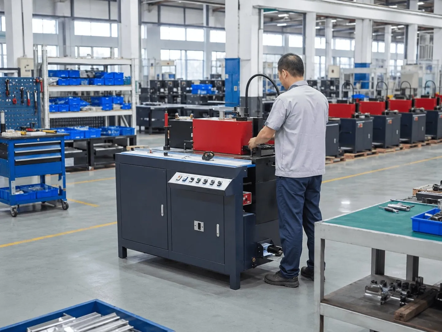
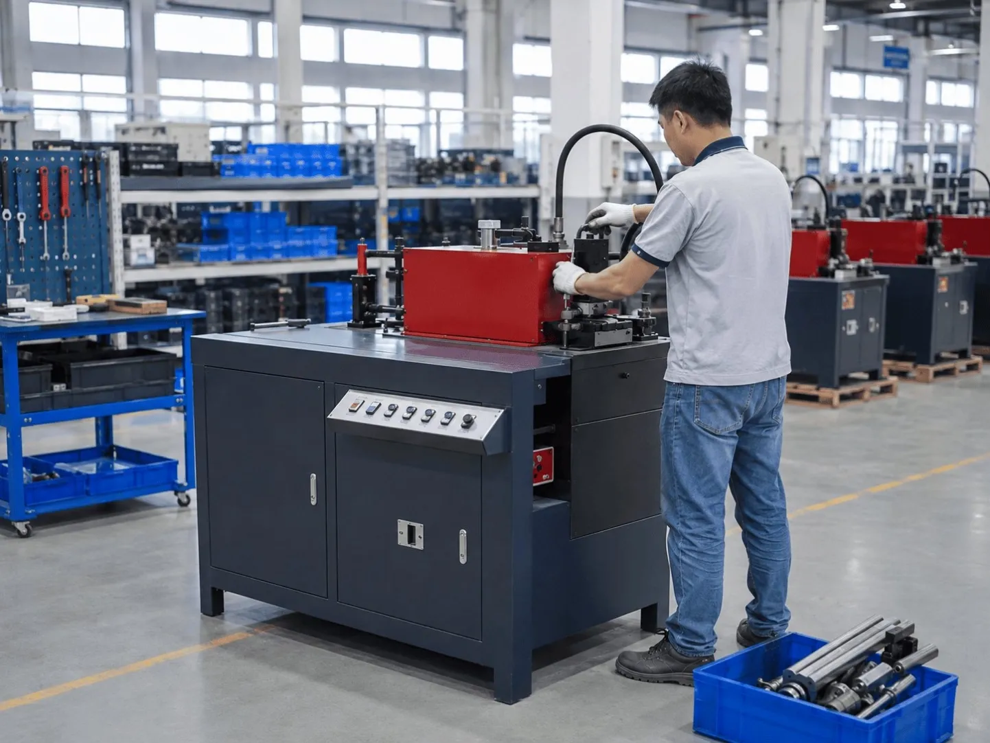
From our Foshan supplier network — these photos show typical enclosure fabrication and panel-assembly steps carried out by our inspected production partners.