
Oct 12, 2026Buying Guides
Electrical Enclosure Layout Guide: Spacing and Zones That Keep the Box Serviceable
Most enclosure failures start on the inside. Here's how to lay out components, spacing, and cable routes so the box stays cool, serviceable, and safe.
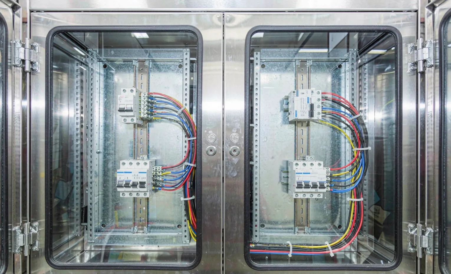
Most enclosure problems don't show up on the outside. They start on the inside—the day someone crammed a VFD, three contactors, and a terminal block into a box two sizes too small and called it done. I've opened enough of those to know: layout is where a good enclosure is won or lost.
You can spec the right IP66 stainless cabinet and still end up with a box that overheats, trips at random, and takes an hour to troubleshoot because nobody can trace a wire. None of that is the steel's fault. It's the layout.
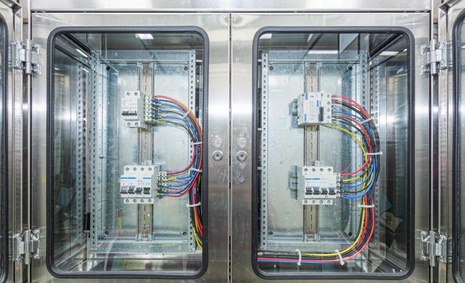
Start with the zones, not the parts.
Before you bolt in a single DIN rail, decide what goes where. I split every enclosure into three zones, and I draw them on paper before the first component goes in.
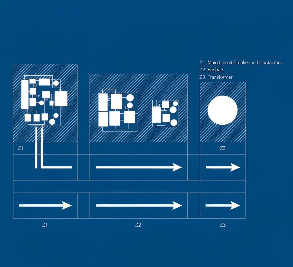
Zone 1—power distribution. Main disconnect, breakers, fuses, and contactors. This is the hot, high-current end. Keep it away from anything sensitive.
Zone 2—control and intelligence. PLC, relays, signal conditioners, the HMI cutout. Low voltage, noise-sensitive. It wants distance from Zone 1.
Zone 3—field termination. Terminal blocks where every cable from the field lands. This is where the electrician spends most of the install time, so it needs the most working room.
Engineering Note: A cabinet is serviceable in proportion to how clearly those three zones are separated. If a tech has to reach across the main disconnect to land a field wire, the layout failed.
Spacing rules that actually matter
Forget the brochure. Here's what keeps a box alive on site.
Leave a fist of air above heat sources. Anything that dissipates real watts—a VFD, a server-grade power supply, a string of contactors—needs clearance above it for convection to work. I leave at least 50 mm, more if the ambient runs hot. A drive jammed against the top plate is a drive that derates itself within a season.
Don't pack the rails. DIN rails look tidy at 100% fill in the catalog. In the field, you want 20–30% free space. That spare slot is where the next modification goes instead of "let's just squeeze it in."
Separate signal from power physically. Run low-voltage signal cables on one side, power on the other. Cross them at 90° if you must cross at all. This single habit kills more ghost faults than any filter you can buy.
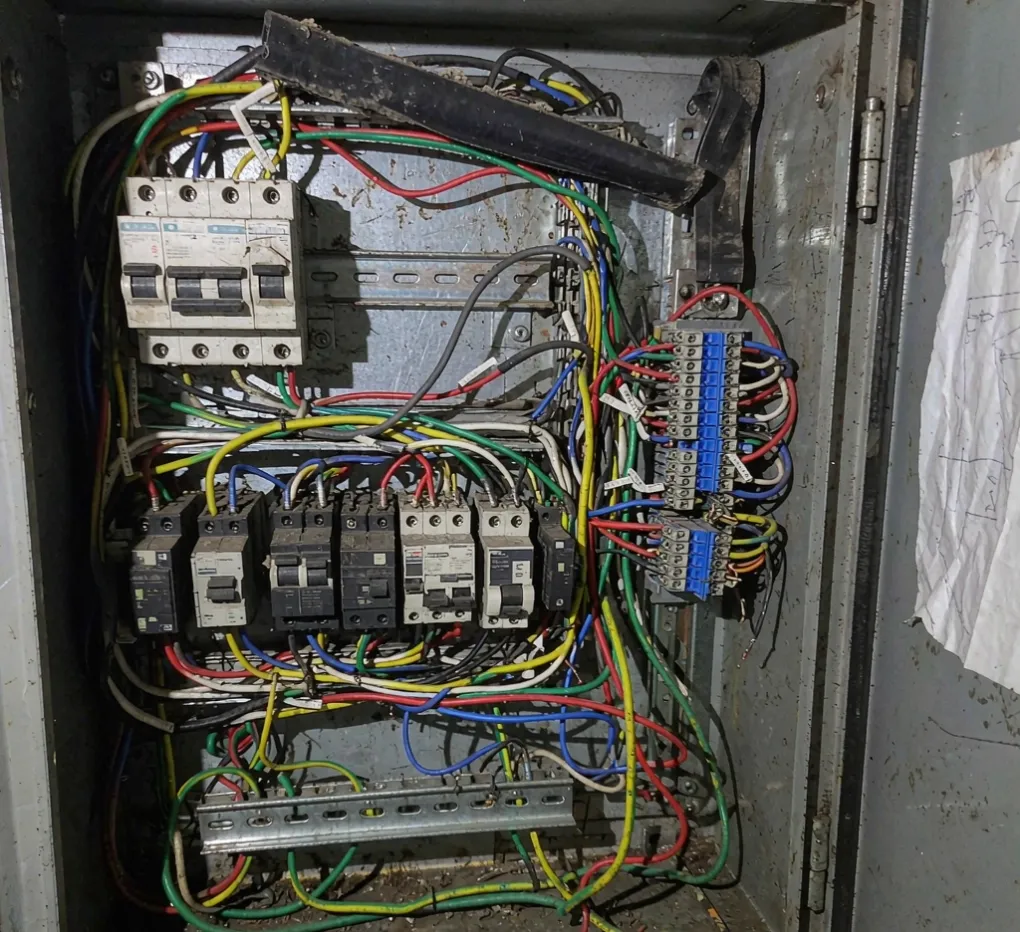
Cable routing is half the job.
People obsess over the panel and forget the cables. Then the door won't close, or a cable chafes on a sharp edge and fails a year later.
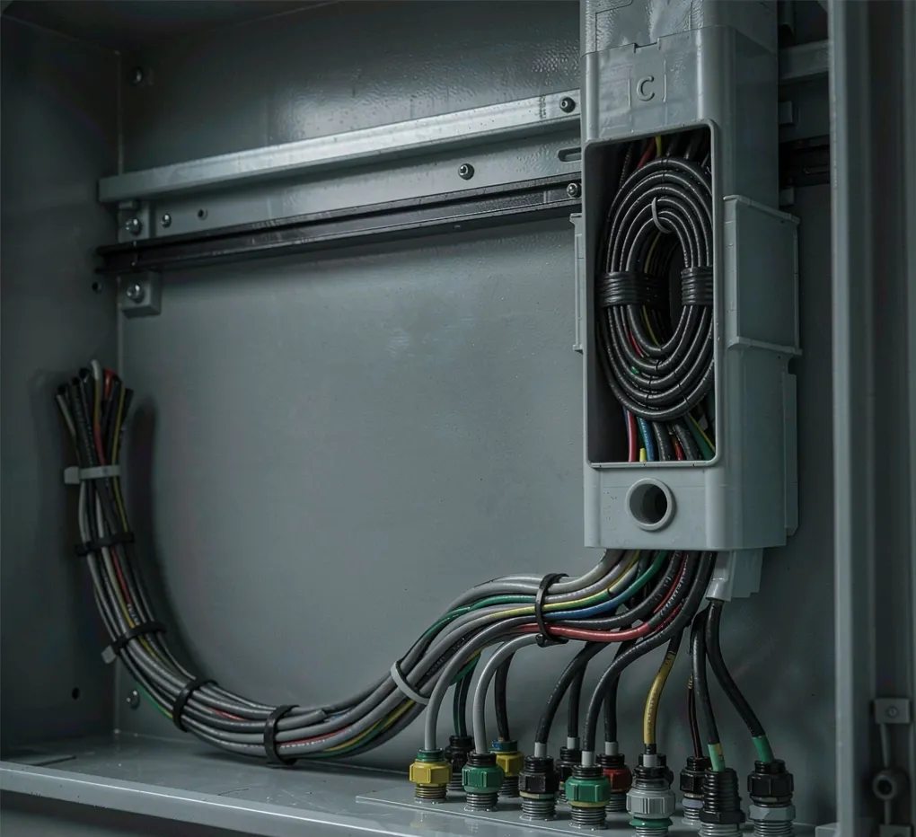
Use the gland plate; don't fight it. Plan your cable entries before you order the box. Group them: power in one quadrant, signals in another, field I/O in a third. Our cable gland selection guide covers the entry hardware; the layout job is deciding how many, where, and what size.
An internal duct is not optional on a real build. Plastic cable ducts on the sides give every wire a home and keep the inside from turning into spaghetti. It also makes the FAT walkthrough boring—which is exactly what you want.
Strain relief for everything. Every cable that moves when the door opens needs a tie-down near the hinge. I've seen a perfectly good enclosure fail because a door cable flexed 10,000 times and let go.
Don't starve the cooling.
Layout and thermal are the same conversation. A cabinet that's sealed tight but packed solid will cook itself even at a modest ambient.
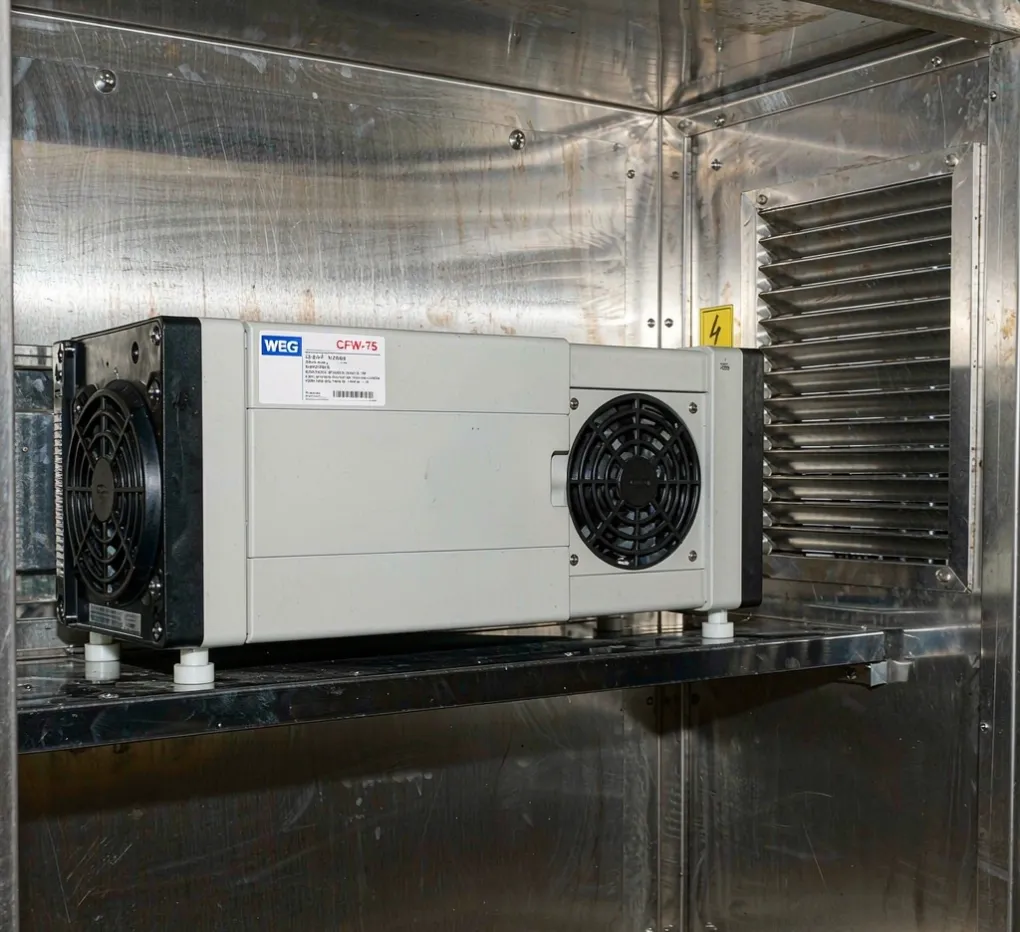
Match the layout to the cooling method. If you're using a fan filter, the air needs a clear path—intake low, exhaust high, nothing blocking it. If you're using a heat exchanger or air conditioner, the hot zone sits against the exchanger face. Our enclosure ventilation and breather guide explains which method fits which site; the layout has to follow that choice.
Mind the gasket. A clean gasket seal only works if the door closes flat. Cables routed through the gasket line, or a component proud of the door frame, breaks the seal, and you're back to condensation. The layout respects the seal line.
The layout rules at a glance
Decision | Do this. | Why it matters |
|---|---|---|
Zones | Power / control / field, separated | Cuts noise faults and speeds service |
Heat clearance | ≥50 mm above heat sources | Prevents VFD/PS derating |
Rail fill | Leave 20–30% free. | Room for the next mod |
Signal vs. power | Separate sides, cross at 90° | Kills ghost trips |
Cable entry | Plan quadrant grouping early. | Clean install, no rework |
Internal duct | Side ducts, strain-relieved | Serviceable, not spaghetti |
A build we fixed at FAT
A packaging OEM sent us a panel where the VFD sat directly above the main disconnect, with the PLC squeezed between them and the signal terminals routed right past the contactor coils. On the bench it ran. In the FAT, with the door closed and the VFD at load, the PLC communication dropped every few minutes. We rebuilt the layout—VFD to the bottom zone, PLC to the opposite side, signal duct fully separated—and it passed a 4-hour soak test clean. Same components, same box. Different layout. That's the whole argument.
What this means for your RFQ
If you're sending us a drawing, great—but the drawing usually shows what goes in, not where. Tell us the zones you care about, the heat sources, and which cables are signal vs. power, and we'll lay it out so it survives commissioning. If you'd rather we propose the layout, that's the normal job.
For the record, we're a sourcing partner and panel-build shop, not a manufacturer of the enclosure steel—so this advice works with whatever cabinet you specify. Our electrical enclosure supplier's guide to sourcing from China covers the broader build-and-ship picture, and our electrical enclosures solution page shows what we integrate and ship.
FAQ
How much free space should I leave in an enclosure? Aim for 20–30% of DIN-rail capacity unused. That spare room is where field changes go instead of forcing a cramped, unreliable retrofit.
Does layout really affect cooling, or just neatness? Both, but cooling is the real one. Blocked airflow paths and heat sources jammed against the top plate force components to derate or trip. The layout is thermal design.
Why separate signal and power cables? Power cables radiate noise that corrupts low-voltage signal lines, causing intermittent trips and comms drops that are nightmares to find. Physical separation is the cheapest fix.
Should I plan cable entries before ordering the box? Yes. Group power, signal, and field I/O entries by quadrant and size them up front. Retrofitting gland plates is rework you can avoid.
How do I make the cabinet serviceable? Three clear zones, side cable ducts, labeled terminal blocks, and strain relief on door cables. If a tech can trace every wire in two minutes, the layout did its job.
What enclosure rating do I need before I even think about layout? That depends on the site—pick the box from IP/NEMA and corrosion needs first, then lay it out. Layout assumes you already chose the right cabinet.
Engineering takeaway
A reliable enclosure is decided on the inside before it's decided on the outside. Three separated zones, real clearance above heat, signal kept away from power, planned cable entries, and internal ducting turn a box of parts into something that passes FAT and survives the field. Skip the layout and you're buying the right steel and throwing the benefit away.
Related guides
Ready to send a drawing? Upload your enclosure layout and component list for an engineering review—we'll return a layout that passes FAT instead of failing on site.