Jul 2, 2026Integration & Compatibility
The Hidden Wiring Problems That Cause Startup Delays in OEM Projects
The Hidden Wiring Problems That Cause Startup Delays in OEM Projects: An Actionable Prevention Guide Every OEM company has experienced this kind of moment before. The machine leaves the workshop look
The Hidden Wiring Problems That Cause Startup Delays in OEM Projects: An Actionable Prevention Guide
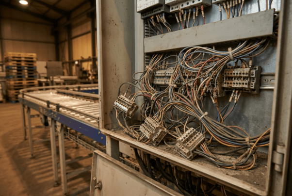
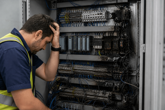
Every OEM company has experienced this kind of moment before. The machine leaves the workshop looking perfect, the FAT has already been signed, the PLC program runs smoothly during testing, and everyone on the project team feels relieved because the shipment finally goes out on time. Then the equipment arrives at the customer site, startup begins, and suddenly the controls team starts receiving messages every few hours about alarms, unstable communication, random shutdowns, or sensors behaving strangely for no obvious reason.
What makes these situations exhausting is not only the technical problem itself. The real pressure comes from the environment around the startup. The customer is waiting for production. The project manager is watching the schedule slip. Service engineers are standing inside a noisy factory at midnight trying to diagnose faults that never appeared during FAT. Meanwhile, everyone starts questioning whether the PLC software has bugs or whether the electrical design was wrong from the beginning.
After enough projects, I realized something uncomfortable. A large percentage of startup delays in OEM projects do not come from complicated automation problems at all. They come from very ordinary wiring details that nobody paid enough attention to during panel assembly.
The difficult part is that these problems usually stay hidden until the machine experiences transportation vibration, electrical noise, temperature changes, or real production conditions for the first time. That is why startup troubleshooting feels so frustrating. The machine looked completely healthy in the workshop, but once it reached the field, small electrical weaknesses began showing themselves one by one.
The Real Cost of Startup Delays Is Bigger Than Most OEMs Admit
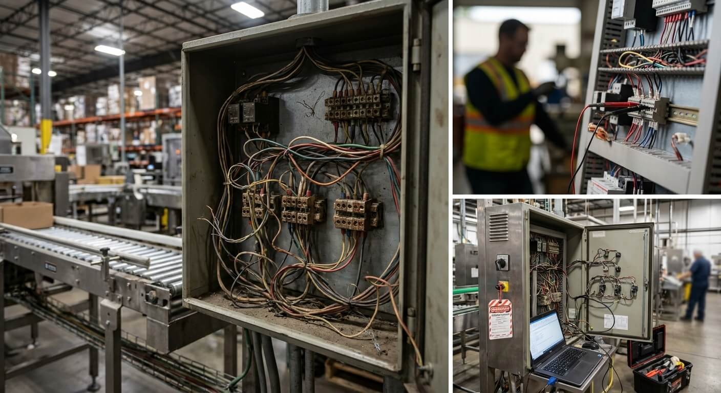
Most people outside the automation industry think startup delays are mainly technical issues. In reality, startup delays quickly become business problems.
When a machine fails to start properly at a customer site, the OEM immediately begins losing money in ways that are not always visible on the project budget sheet. Engineers who should be supporting new projects suddenly spend days doing emergency troubleshooting. Flights get booked at the last minute. Hotel stays get extended. Customers start questioning the reliability of the machine long before production even begins.
What makes this worse is that many of these failures could have been prevented much earlier during panel manufacturing.
I still remember one packaging machine project where the customer kept reporting intermittent servo faults during startup. The alarms appeared randomly. Sometimes the machine would run for six hours without problems. Other times, the servo drives would suddenly lose enable status within minutes after startup. The controls team spent almost two days reviewing PLC logic and drive parameters because the faults looked intelligent enough to be software-related.
The real problem ended up being a loose 24VDC terminal connection inside the control panel that had weakened during transportation.
That tiny wiring issue delayed startup for nearly a week.
Experiences like that completely changed how we think about electrical workmanship.
Loose Connections Usually Do Not Fail Immediately
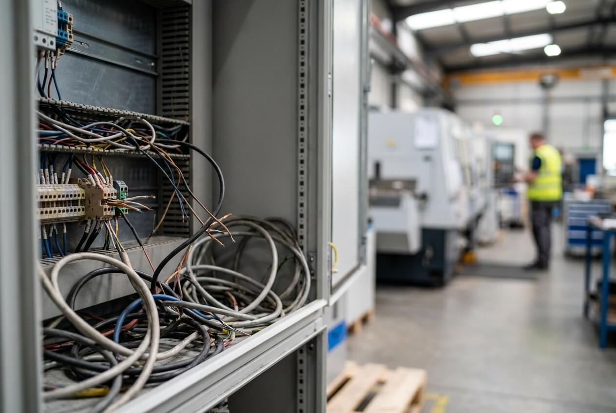
One of the most dangerous things about poor wiring connections is that they often work perfectly during initial testing. That is why these problems survive FAT and only appear later during startup.
Inside many control panels, stranded wires are still terminated directly into terminal blocks without ferrules. At first glance, this does not look like a serious issue because the wire feels tight after assembly and the circuit powers on normally during workshop testing. The problem begins after transportation vibration, temperature cycling, and repeated machine operation start affecting the connection pressure.
When stranded wire gets compressed unevenly under a terminal screw, the conductor slowly changes shape over time. Some strands flatten harder than others, some strands spread outward slightly, and eventually the contact pressure becomes inconsistent. Once that happens, the connection starts behaving unpredictably under vibration or electrical load.
The frustrating part is that these failures are intermittent in the beginning. The machine does not simply shut down completely. Instead, signals disappear briefly, communication faults appear randomly, or analog values start fluctuating for no obvious reason.
Those are the worst kinds of startup problems because they waste enormous amounts of troubleshooting time.
After dealing with enough of these failures, we stopped treating ferrules as optional accessories. Every stranded control wire now receives an insulated ferrule before termination. We also started performing random pull-force testing during assembly because visually checking a crimp is not enough. A wire can look perfectly acceptable and still fail mechanically after shipment.
Some technicians initially complained that these extra steps slowed down panel assembly. They were right. The process did become slower. But startup reliability improved enough that the tradeoff became obvious very quickly.
Electrical Noise Problems Usually Start with Cable Routing
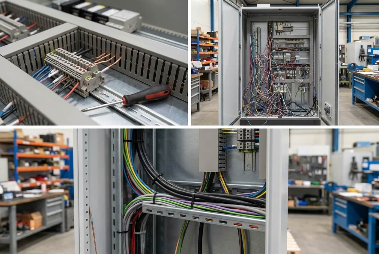
Another problem that causes endless confusion during startup is electrical noise.
What makes EMI problems difficult is that they rarely look like wiring issues at first. Instead, they usually appear as unstable communication behavior or inconsistent sensor readings.
One customer once called us because their machine kept losing Profinet communication every time a hydraulic motor accelerated. At first, everyone suspected the PLC network configuration because the communication faults appeared directly on the HMI diagnostics page. The controls engineer spent hours reviewing switch settings and network parameters before anyone opened the panel to inspect the cable routing itself.
Inside the enclosure, the Ethernet communication cables had been routed tightly alongside 480V motor output wiring for almost the entire panel length.
That was the real problem.
Variable frequency drives generate a large amount of high-frequency electrical noise during operation. When high-voltage motor cables run parallel to low-voltage communication wiring, electromagnetic interference slowly couples into the signal circuits. The longer the cables run together, the worse the interference becomes.
A lot of technicians know that “power cables” and “signal cables” should stay separated, but many people underestimate how sensitive modern industrial communication systems have become. Ethernet-based industrial networks, encoder feedback wiring, analog signals, and remote IO communication are much less forgiving than older relay-based systems.
Now we separate high-voltage and low-voltage wiring aggressively inside every panel layout. If cables absolutely must cross, they cross at 90 degrees instead of running parallel together. This sounds like a small layout detail, but it prevents many startup communication problems before the machine ever leaves the shop.
We also changed how shield grounding[^1] is handled because many panels still use pigtail grounding methods[^2] for shielded communication cables[^6]. That approach is convenient during assembly, but it performs poorly in high-noise environments[^5]. We now use proper 360-degree shield grounding clamps[^3] mounted directly to the grounding bar because the shielding becomes much more effective when the electrical noise has a proper discharge path. [^4]
The difference becomes obvious very quickly once multiple VFDs start operating simultaneously.
Torque Problems Create Failures That Nobody Notices During Assembly
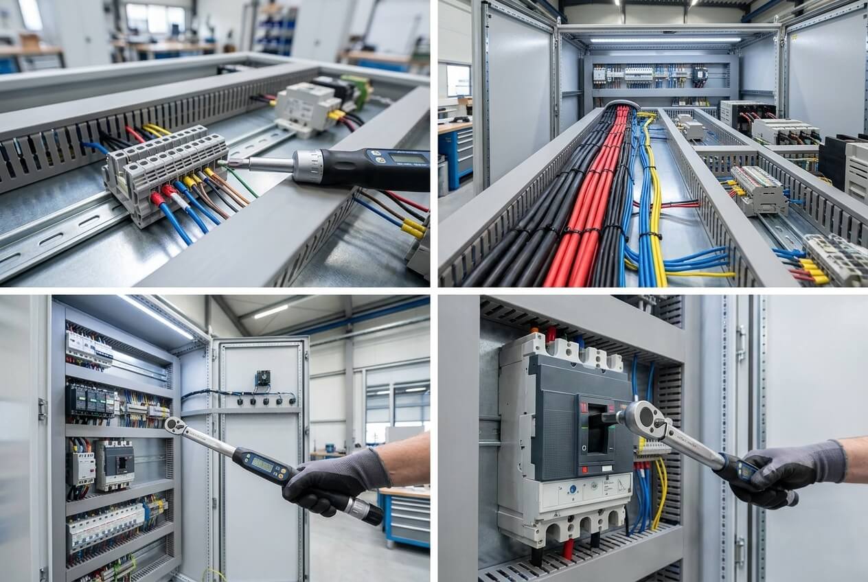
One uncomfortable truth inside panel manufacturing is that many wiring terminations are still tightened entirely based on technician experience.
A worker installs a breaker, tightens the terminal “until it feels right,” and moves to the next component.
The problem is that modern control panels no longer tolerate that level of inconsistency very well.
Today’s automation systems contain much higher wiring density than older industrial panels. Components are smaller, terminals are more compact, and current loads are often concentrated into tighter spaces. Under those conditions, terminal torque matters much more than many people realize.
If a terminal is too loose, electrical resistance increases and the connection becomes unstable under load. If the terminal is too tight, the wire ferrule can deform, the conductor can become damaged, or the terminal body itself can crack internally. In many cases, the connection still passes continuity testing initially, which is why these problems survive workshop inspection.
We learned this lesson during a servo control project where intermittent enable faults kept appearing after startup. The root cause ended up being an over-tightened terminal connection that had partially damaged the ferrule during assembly. The wire remained electrically connected most of the time, but vibration and thermal expansion caused occasional signal interruption once the machine started running continuously.
After that experience, we stopped allowing uncontrolled torque assembly on critical terminals. Every technician now uses calibrated torque screwdrivers matched to the manufacturer specifications. Important power connections also receive torque seal marking after installation so maintenance teams can visually detect movement later.
This process added more discipline to assembly work, but it removed a huge amount of uncertainty during commissioning.
Wiring Documentation Problems Become Disasters During Troubleshooting
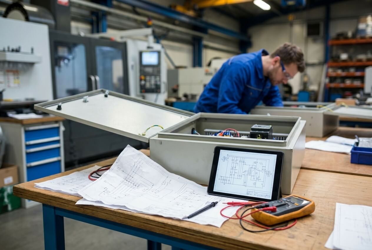
One of the most frustrating startup situations happens when the physical wiring no longer matches the electrical drawings.
This problem appears constantly in OEM projects because machines evolve quickly during FAT and debugging. IO points get reassigned. Sensors move to different terminals. Temporary modifications become permanent solutions. Meanwhile, everyone assumes the drawings will get updated later.
Sometimes they do, and sometimes they will never happen.
I remember one machine where the startup team spent nearly half a day troubleshooting the wrong pressure sensor because the as-built drawings no longer matched the actual wiring inside the panel. During FAT, one analog input channel had been temporarily reassigned to solve a testing problem. The machine eventually shipped with the updated wiring configuration, but the documentation package was never corrected before delivery.
Nothing was technically broken.
The PLC logic was correct.
The field device worked properly.
The wiring itself was functional.
The only problem was that the documentation no longer reflected reality.
That alone was enough to create major startup confusion.
After enough situations like this, we completely changed how documentation updates are managed. Any wiring modification made during FAT or debugging now has a strict update deadline before shipment approval can happen. We also moved toward heat-shrink wire markers because temporary adhesive labels often become unreadable after exposure to heat, oil, or cleaning chemicals.
Good documentation sounds boring compared to advanced automation technology, but during startup troubleshooting, accurate drawings often matter more than sophisticated software diagnostics.
The Pre-Shipment Checks That Actually Prevent Startup Delays
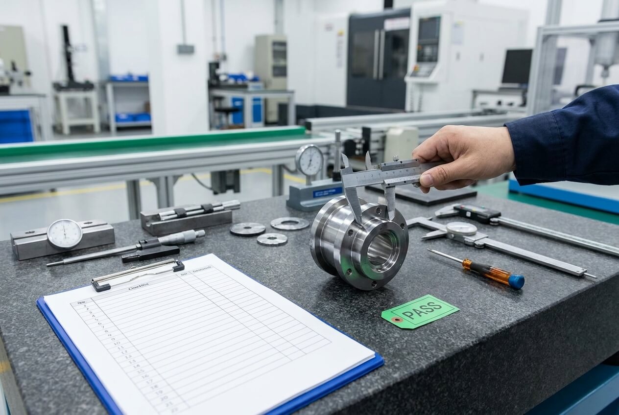
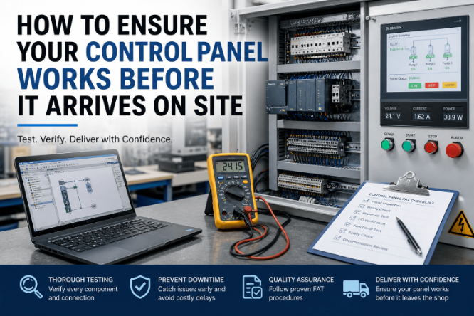
Over time, we realized that many OEM FAT procedures focus heavily on machine functionality while paying far less attention to wiring workmanship quality. A machine can complete a production cycle successfully during FAT and still contain electrical weaknesses that only appear after transportation and installation.
That realization forced us to redesign our final inspection process.
Now every control panel goes through several additional verification steps before shipment.
We perform full continuity testing against the electrical schematics because wiring mistakes hidden behind successful machine operation are still wiring mistakes. We perform insulation resistance testing using a megohmmeter on main power circuits because damaged insulation may not become obvious until the machine operates under real load conditions.
We also perform random mechanical tug testing on wire terminations because weak crimps often survive visual inspection.
Ground bonding verification became another major focus because poor grounding quality contributes heavily to communication instability and electrical noise problems. We now verify that enclosure doors, grounding bars, and panel structures maintain low-resistance continuity instead of assuming the mechanical mounting hardware alone provides acceptable grounding.
These checks do require additional manufacturing time.
But they reduce startup firefighting dramatically.
Conclusion
Most startup delays in OEM projects do not begin with advanced automation failures. They begin with ordinary electrical workmanship problems that stay hidden until the machine reaches real operating conditions.
Loose terminations, poor cable routing, uncontrolled torque, and inaccurate wiring documentation sound like small details when a machine is still inside the workshop. Once the equipment arrives at a customer site, those same details can delay production, exhaust engineering teams, and damage customer confidence very quickly.
The automation industry spends a lot of time discussing software innovation, digitalization, and smart manufacturing technologies, but many successful startups still depend on very traditional electrical discipline.
Good automation systems are not only designed well.
They are wired well, documented properly, and assembled with enough care that they continue operating reliably long after the FAT is over.
If your project is approaching startup and you’re trying to avoid onsite commissioning problems, feel free to send us your panel drawings, BOM, or system requirements before shipment.
We’ll help review potential wiring, compatibility, and deployment risks before they become startup delays onsite.
Additional FAQ
Why do wiring problems often appear only after the machine reaches the customer site?
This happens because many wiring defects are mechanically weak but electrically functional during workshop testing. Inside the factory, the machine usually operates in a controlled environment for a short period of time. Once the equipment is shipped, the panel experiences vibration, temperature changes, handling stress, and real production loads for the first time.
A slightly loose terminal or weak crimp may survive FAT without any obvious symptoms, but after transportation and startup vibration, the connection quality starts degrading. That is why many startup issues seem random in the beginning.
The machine technically worked before shipment, but the wiring was never robust enough for real operating conditions.
Why are intermittent faults harder to diagnose than complete failures?
Complete failures usually leave a clear trail because the device stops working entirely. Intermittent faults behave differently. The signal disappears briefly, communication drops for a few seconds, or a drive trips only under certain operating conditions.
This creates confusion because the machine sometimes works normally and sometimes fails without a consistent pattern.
In many OEM projects, intermittent faults are caused by:
- weak terminal pressure,
- vibration-sensitive wiring,
- unstable grounding,
- electrical noise,
- or damaged conductors inside the insulation.
The troubleshooting process becomes difficult because the problem may disappear temporarily while engineers are testing the machine.
Why do communication networks fail when VFDs start running?
Variable frequency drives generate high-frequency electrical noise during motor switching. If communication cables are routed too close to motor power cables, electromagnetic interference can couple into the network wiring.
The problem becomes more severe when:
- Ethernet cables run parallel to motor cables.
- shielding is grounded incorrectly,
- panel grounding quality is poor,
- or multiple VFDs operate inside the same enclosure.
Many engineers initially suspect PLC programming or network configuration because the symptoms appear as communication faults. In reality, the root cause is often electrical noise entering the signal wiring physically.
Are ferrules really necessary inside modern control panels?
In most industrial control panels, yes.
Without ferrules, stranded wire compresses unevenly under terminal screws. Over time, vibration and thermal cycling reduce connection pressure and create unstable electrical contact.
Ferrules create a stable mechanical interface between the wire and the terminal block, which improves long-term reliability significantly.
This becomes especially important for the following:
- low-voltage control wiring,
- safety circuits,
- analog signals,
- and communication wiring.
Panels without ferrules may still work initially, but they are usually much more vulnerable to long-term startup and vibration-related issues.
Why does poor grounding create communication problems?
Many people think grounding only matters for electrical safety. In modern automation systems, grounding also affects signal stability.
Poor grounding creates unstable electrical reference points inside the control system. Once VFDs, servo drives, or switching power supplies begin operating, electrical noise may travel through communication wiring and sensitive signal circuits instead of dissipating safely through the grounding system.
This can lead to:
- network instability,
- encoder errors,
- analog signal fluctuation,
- HMI freezing,
- or random PLC communication faults.
A properly designed grounding system improves both safety and automation reliability.
What is the biggest mistake? OEM panel builders make during FAT?
One of the biggest mistakes is focusing only on whether the machine functions instead of verifying whether the wiring workmanship is reliable long-term.
A machine may complete a successful FAT cycle while still containing:
- weak crimps,
- poor shield grounding,
- loose terminals,
- incorrect torque,
- or undocumented wiring modifications.
Those issues often stay hidden until the machine experiences real transportation vibration and full production operation.
A good FAT process should verify not only machinebehavior butt also electrical assembly quality.
Why do inaccurate electrical drawings create major startup delays?
During startup troubleshooting, engineers depend heavily on electrical drawings to isolate faults quickly. If the drawings no longer match the real panel wiring, troubleshooting becomes extremely slow and confusing.
In many OEM projects, wiring changes happen during FAT and debugging, but the as-built documentation never gets updated properly before shipment.
Once the machine arrives onsite, nobody trusts the drawings anymore.
At that point, engineers start manually tracing wires inside the cabinet, which wastes enormous amounts of startup time.
Accurate documentation is not administrative paperwork. It is part of machine maintainability.
How can OEMs reduce startup troubleshooting time significantly?
The biggest improvement usually comes from tightening manufacturing discipline before shipment.
That includes:
- using ferrules consistently,
- controlling terminal torque,
- separating power and signal wiring properly,
- verifying shield grounding,
- updating as-built documentation immediately,
- and performing real electrical workmanship inspections during FAT.
Most startup delays are preventable if the panel manufacturing process treats wiring quality as seriously as PLC programming.
What should customers ask before approving a control panel FAT?
Customers should ask questions that go beyond basic machine operation.
For example:
- Were terminal torques verified using calibrated tools?
- Were communication shields grounded correctly?
- Was insulation resistance testing completed?
- Were wiring modifications updated in the as-built drawings?
- Were random tug tests performed on wire terminations?
- Was cable segregation reviewed for EMI protection?
These questions usually reveal whether the OEM focuses only on functionality or also cares about long-term reliability after installation.
Related Products:
Related Articles: