
Sep 24, 2026Control Panels
Why Grounding Problems Cause Random Faults in Control Panels
Random faults that move when you reseat a wire are usually grounding, not PLC failure. Three causes we see most often, the checks that find them, and the FAT tests that catch them before shipment.
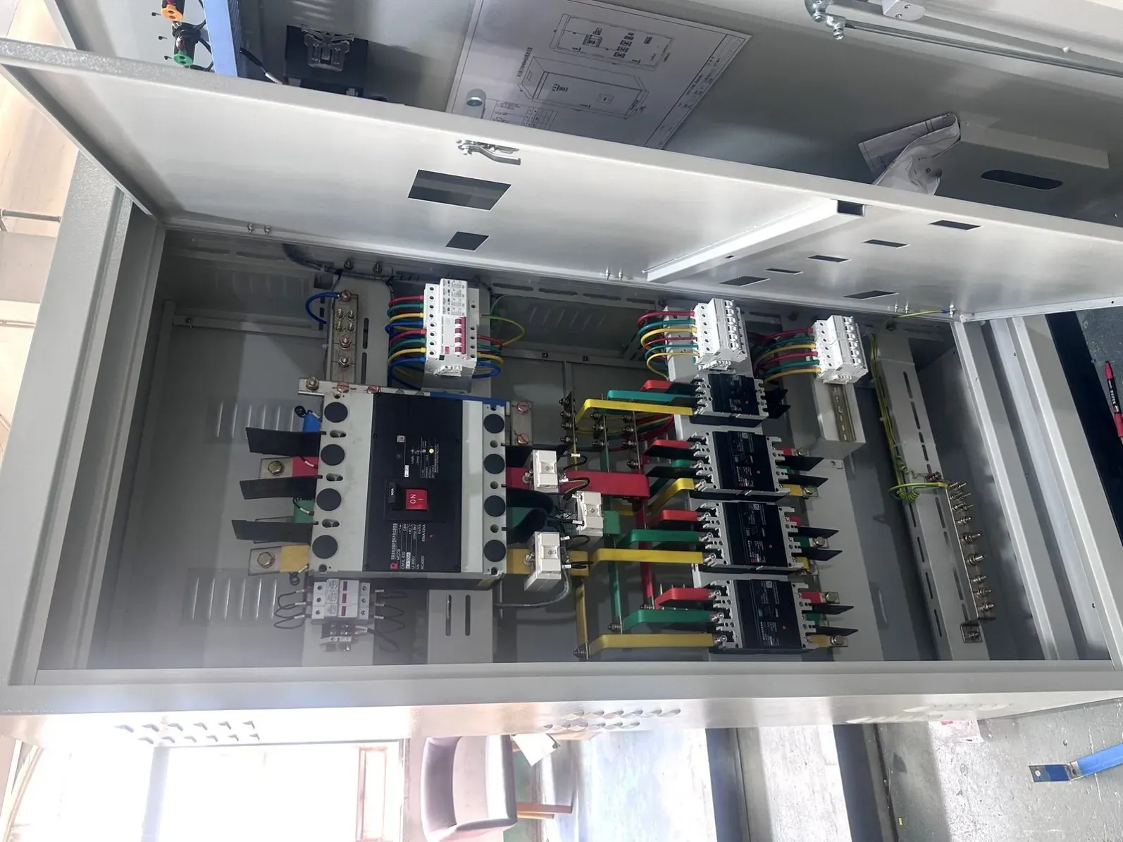
Random faults that appear and disappear, move when you touch a wire, or only show up when a VFD ramps — that pattern is almost never a failing PLC. In the panels we build and see in the field, it is one of three grounding and bonding problems: a shield bonded at both ends, a protective bonding path broken by paint or gaskets, or VFD common-mode current with nowhere clean to go. Each one mimics a "bad component," which is why so many panels get new PLCs, new power supplies, and new I/O cards before anyone measures a bond.
This article covers the three causes we see most often in imported and locally built panels, the specific check that finds each one, and the FAT tests that catch them before the panel ships.
Cause 1: Analog shields bonded at both ends
What it looks like: 4–20 mA signals that drift a little at a time — a level transmitter reading 3% high in the afternoon, a pressure input that jumps when a nearby drive starts. Loop resistors, power supplies, and even the transmitter get replaced. The drift comes back.
The mechanism: if the shield drain wire of an analog cable is bonded to ground at both the panel and the field device, the two bond points sit at slightly different potentials. That difference drives a current through the shield, and the shield couples it straight into the measurement pair. On a 4–20 mA loop, a shift of just 0.5 mA is already 3% of span — visible on any trend. VFD loads make it worse because they raise the noise floor on the whole PE system.
The check: with the loop disconnected at one end, measure AC millivolts between the shield and local PE. Anything more than a few tens of millivolts under load means shield current. Fix: bond the shield at one end only (normally the panel side) and insulate the field end — or use an isolator on the analog input.
Cause 2: Protective bonding broken by paint, gaskets, and door hinges
What it looks like: the panel runs fine for months, then random resets, HMI freezes, or an earth-fault alarm that never repeats when the inspector is watching. Nothing you swap changes it.
The mechanism: a bolted enclosure relies on metal-to-metal contact for protective bonding. Powder-coated flanges, gasketed doors, and hinged-mounted components break that contact. The door looks grounded because the hinge touches, but a hinge is a spring, not a conductor — its impedance rises the moment paint wears or vibration settles in. Door-mounted drives and HMIs then float relative to the panel PE, and their noise floor rises with it.
The check: IEC 60204-1 requires a protective bonding continuity test with a test current of at least 10 A, and a resistance of no more than 0.1 Ω is the accepted limit between the PE terminal and any bonding point. A normal multimeter cannot do this — it needs a low-reading milliohm meter. In practice: bonding jumpers across every door, every backplate, and every gland plate, then measure, not assume.
Cause 3: VFD common-mode current with nowhere clean to go
What it looks like: the panel is quiet until a drive ramps, then analog inputs jitter, a safety relay drops once a week, or the PLC reboots with no fault code. The drive itself reports nothing wrong.
The mechanism: a VFD switches at 2–16 kHz, and its output pulses charge the capacitance of the motor cable. That common-mode current has to return to the drive. If the cable shield is terminated with a pigtail — a few centimeters of drain wire screwed to a terminal — the high-frequency return path is blocked, and the current finds another way: through the analog 0 V reference, through instrument shields, through anything. The result is noise exactly where your measurement signals live.
The check: every VFD motor cable shield must be terminated 360° — EMC gland or full-circumference clamp at both the drive and the motor end. Then route the motor cable away from analog wiring, and confirm the drive's PE lands on the same bar your clean grounds use, not on a door hinge.
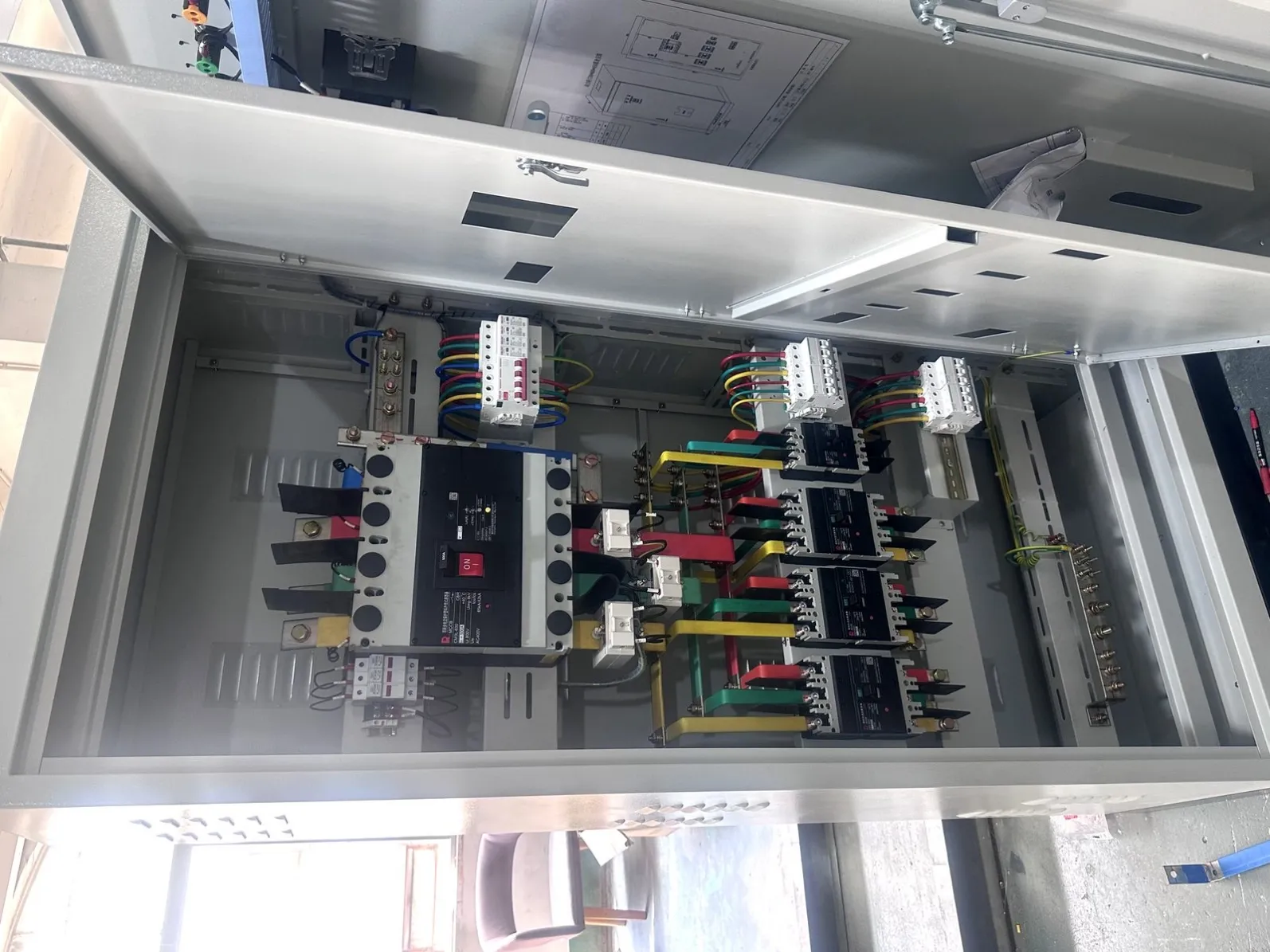
The 8-point triage checklist
Run this in order on any panel with moving faults:
- Note the pattern: does the fault correlate with a drive ramp, a door opening, or a specific feed? (Do this before touching anything.)
- Measure AC millivolts between each analog cable shield and panel PE — under load, not powered down.
- Confirm every analog shield is bonded at one end only; insulate the far end.
- Measure PE bonding with a milliohm meter (10 A source where possible): PE terminal to backplate, to door, to gland plate. Anything above 0.1 Ω needs a bonding jumper.
- Check every door, backplate and gland plate for a dedicated bonding jumper — hinges do not count.
- Inspect VFD motor cable shield terminations: 360° clamp or EMC gland at both ends, no pigtails.
- Separate VFD motor cables from analog and network wiring; crossings at 90° only.
- After the fix, power-cycle and run the load cycle that used to trigger the fault — twice.
How this gets caught before shipment
Most of the above is testable in the shop, which is why we insist on it. Every panel we build goes through Factory Acceptance Test (FAT) before packing, and the records include protective bonding continuity at ≥10 A against the 0.1 Ω limit and 500 V DC insulation resistance — the two tests that expose causes 2 and 3 while they are still cheap to fix. The results ship with the panel, so your inspection team can re-verify on arrival.
A few practical notes for buyers:
- Complete panels are built to your drawings from 1 unit (prototype or project orders), typically 35–40 days after drawing and BOM review.
- Empty enclosures — carbon steel, 304/316 stainless or galvanized, IP65/NEMA 4X — run from 5 units, 15–20 days fabrication.
- For panels destined for UL markets, we source through UL-listed partner workshops on request.
To be clear about scope: we are a sourcing and build partner — we build and test to your drawings, including your grounding and bonding scheme. System design, PLC programming and on-site commissioning stay with you or your integrator. If your drawing marks shield-bonding or bonding-jumper points, we build exactly to them; if it does not, our default is the scheme above, and we flag it in the FAT records.
Questions buyers ask before ordering
Can you build to our grounding specification instead of yours?
Yes. Send the bonding scheme with the drawings and we build to it — one-end shield bonding, clean-ground separation, jumper locations, all of it. If something in your scheme conflicts with IEC 60204-1, we raise it before the build starts, not after the FAT.
Do you test grounding on every unit or just the first article?
Every unit. The PE continuity and insulation resistance tests are part of routine FAT, and the measured values are recorded per panel, not copied from a template.
We already have a panel with these symptoms. Can you fix it?
We can rebuild or rework a panel to your corrected drawing — new bonding jumpers, re-terminated shields, separated cable routing. Diagnosing an already-installed panel on your site is integrator work, which we do not do.
What do you need from us to quote a replacement panel?
Drawings or even a marked-up photo set, the BOM if you have it, and the environment rating (IP/NEMA) you need. See our panel build service for what a typical order package looks like.
How does this show up in the FAT records we receive?
Each FAT record lists the protective bonding resistance values measured at the defined points, the insulation resistance result at 500 V DC, and the functional test summary. You get the document set with the panel, so acceptance on your side is verification, not discovery.
Do stainless enclosures change any of this?
No — bonding rules are identical. Stainless helps corrosion long-term, and our enclosure line covers both, but paint, gaskets and hinges break continuity on stainless doors the same way they do on carbon steel.
Where to go next
If your panel passed FAT but faults started after installation, that is a different problem with different causes — see why a control panel passes FAT but fails on site. For the wiring-level version of the same story, read hidden wiring problems that cause startup delays in OEM projects.
To talk through a panel build or a rework, send your drawings and requirements through our contact page — prototype orders from 1 unit.