Jul 2, 2026PLC & Automation Systems
Why PLC Communication Problems Appear During Commissioning
Why PLC Communication Problems Appear During Commissioning—and 4 Steps to Fix Them Forever PLC communication problems almost never appear at a convenient time. They usually show up during commissioni
Why PLC Communication Problems Appear During Commissioning—and 4 Steps to Fix Them Forever
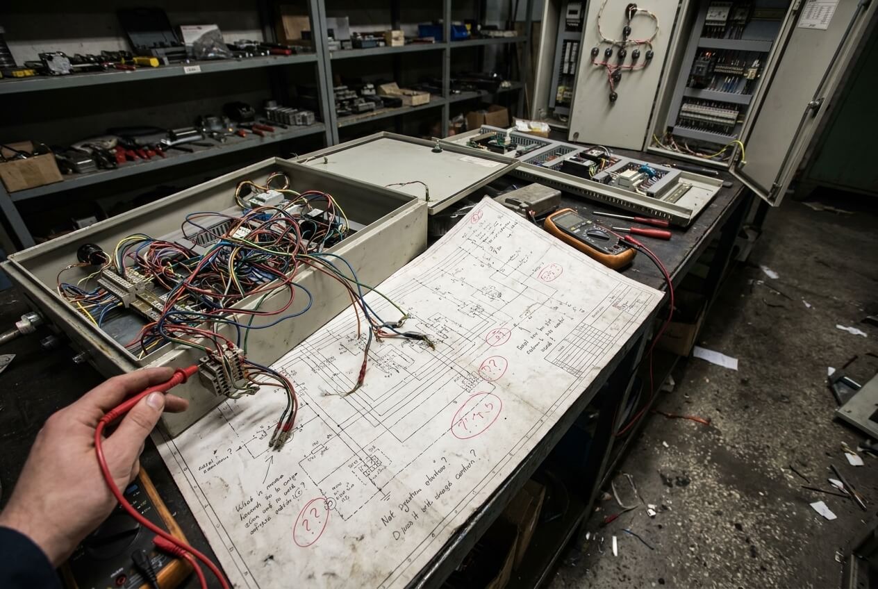
PLC communication problems almost never appear at a convenient time. They usually show up during commissioning, when the machine is already onsite, the customer is waiting for production, and everyone in the room is watching the controls engineer for answers.
The frustrating part is that communication failures rarely look consistent in the beginning. One moment the network is stable, the next moment the HMI freezes, a remote IO station disappears, or the PLC suddenly loses communication with a drive that worked perfectly during FAT.
Most engineers react the same way at first. They restart the PLC, unplug network cables, power-cycle the switch, or change communication settings randomly, hoping the problem disappears. Sometimes the system comes back temporarily, which makes the troubleshooting even more confusing because nobody understands what actually fixed the issue.
After enough commissioning projects, I realized something important. Communication failures are usually not mysterious software problems. They are physical problems caused by noise, grounding, cable routing, topology mistakes, or unstable electrical environments.
The field environment is completely different from the workshop. Once the machine reaches a real factory, the communication system suddenly has to survive VFD noise, long cable distances, shared grounding systems, poor plant power quality, and unpredictable network traffic coming from equipment nobody controlled during design.
That is why communication systems that looked stable during FAT suddenly fall apart during startup.
The good news is that these failures usually follow recognizable patterns. Once you understand the physical behavior behind the problem, troubleshooting becomes much faster and much less emotional.
Problem #1: VFD Noise Is Destroying the Communication Network
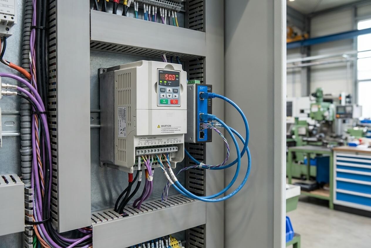
One of the most common commissioning problems happens when communication fails every time a VFD starts running.
This problem appears constantly in industrial environments because VFDs generate large amounts of high-frequency electrical noise during motor switching. That electrical noise spreads through nearby wiring, grounding systems, and even enclosure metal structures if the installation was not designed carefully.
The symptoms usually look very specific once you learn to recognize them.
The PLC network works normally while the motors are stopped. Then the moment a drive accelerates, communication alarms begin appearing. Sometimes the HMI freezes briefly. Sometimes remote IO drops offline for a few seconds. Sometimes Modbus packets start timing out randomly.
Then the drive stops running, and suddenly everything looks normal again.
At first glance, many engineers assume the communication protocol settings are wrong because the network itself appears unstable. In reality, the protocol is usually fine. The physical electrical environment is the problem.
What We Do First During Emergency Troubleshooting
The fastest temporary fix is usually very simple.
We physically separate the communication cable[^1] from the motor power cables[^2] immediately, even if the routing becomes messy temporarily. In many cases, we literally pull the Ethernet[^3] or RS485 cable[^4] out of the wire duct and suspend it away from the VFD output wiring[^5] just to test whether electrical noise[^6] is the real issue.
If the communication stabilizes after separation, the diagnosis becomes obvious very quickly.
We also inspect shield grounding immediately because many installations still terminate shielding incorrectly. One of the most common mistakes is grounding the shield with a small “pigtail” wire. That method might look acceptable electrically, but at high frequencies it performs poorly because the noise does not dissipate effectively.
Now we always use proper 360-degree shield grounding clamps connected directly to the grounding bar. Once the shielding contacts the grounding system correctly around the entire cable circumference, the improvement in communication stability is usually immediate.
The Long-Term Fix Is to Reduce Noise at the Source
Temporary cable separation helps during commissioning, but it does not solve the real problem permanently.
The better solution is reducing the VFD noise before it spreads through the system.
That is why we now install ferrite cores and line reactors much more aggressively on VFD installations, especially in projects with sensitive communication networks or long cable runs.
A ferrite core helps absorb high-frequency noise directly on the cable, while a line reactor reduces harmonic distortion and switching noise generated by the drive itself.
This becomes extremely important in facilities where multiple drives operate simultaneously because the electrical noise from several VFDs can combine into a much larger problem.
One water treatment project taught us this lesson very clearly. During commissioning, every Modbus device near the pump drives started dropping communication randomly whenever the motors ramped above 40Hz. At first, the controls team spent almost an entire day reviewing PLC logic because the communication faults looked inconsistent.
The real issue turned out to be unfiltered VFD output noise coupling directly into the communication wiring inside the enclosure.
After adding ferrite suppression and rerouting the communication cables, the network stabilized immediately.
Problem #2: RS485 Communication Fails at Long Distances
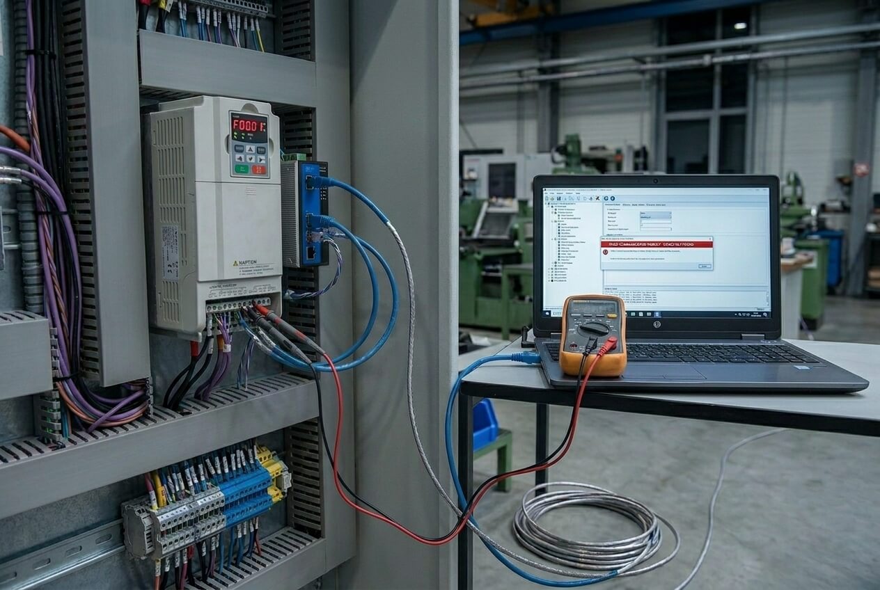
RS485 and Modbus RTU systems can work very reliably, but only if the wiring topology is correct.
Unfortunately, many field installations are not wired correctly.
One of the most common patterns appears when devices closest to the PLC communicate normally while devices farther away begin losing packets, responding intermittently, or disappearing entirely.
This usually happens on cable runs longer than 50 to 100 meters, especially when installers create star topologies or long branch connections instead of a proper daisy-chain network.
The frustrating part is that the network often works “most of the time,” which makes troubleshooting confusing.
Why Signal Reflection Causes Random Failures
RS485 communication behaves very differently from ordinary point-to-point wiring.
When the cable reaches long distances, communication signals begin reflecting back through the line if the network impedance is not controlled properly.
Those reflected signals interfere with the original communication data and create packet corruption.
This becomes worse at higher baud rates because the signal edges become sharper and more sensitive to reflections.
The First Thing We Check Onsite
During commissioning, the first emergency fix is checking for proper termination resistors.
A 120Ω resistor should exist at the following:
- the physical beginning of the network
- and the physical end of the network
Not in the middle.
Not on every device.
Only at the two ends.
It is surprising how many installations either forget termination completely or enable termination switches randomly on multiple devices.
Once the reflections become severe, communication reliability drops dramatically.
If packet loss continues even after proper termination, we temporarily reduce the baud rate immediately.
Many systems ship configured at 115.2 kbps because engineers want fast communication updates, but during commissioning stability matters more than speed.
Dropping the baud rate to 19.2 kbps often stabilizes a struggling network very quickly because slower communication tolerates reflections and electrical noise much better.
The Real Fix Is Correct Network Topology
The permanent solution is always proper wiring topology.
RS485 networks should follow a clean daisy-chain structure from device to device.
What should never happen is a star topology where multiple devices branch outward from one central point. Long branch connections create reflections that become extremely difficult to control once cable distances increase.
I have seen installers unknowingly create communication problems simply because the star layout looked cleaner mechanically inside the panel.
Electrically, it was a disaster.
Good RS485 wiring sometimes looks less visually perfect, but it behaves much more reliably in the field.
Problem #3: Industrial Ethernet Networks Collapse After Connecting to the Plant Network
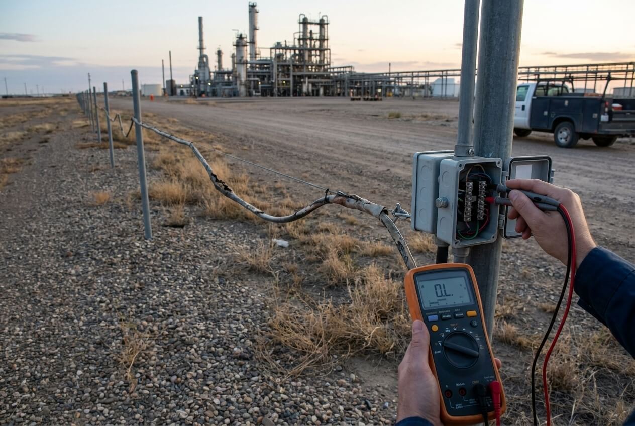
This problem creates panic very quickly because the entire control system suddenly feels unstable.
The HMI becomes slow.
PLC communication lights flash constantly.
Network devices appear and disappear randomly.
Engineering laptops struggle to stay connected.
The strange part is that everything worked correctly before the machine connected to the factory network.
That detail is extremely important.
In many facilities, the industrial automation network becomes contaminated by the larger IT network environment once the systems connect together.
The Fastest Way to Diagnose the Problem
The quickest emergency troubleshooting step is isolation.
We disconnect the cable linking the machine network to the factory network immediately.
If the PLC, HMI, and drives suddenly stabilize once isolated, the problem is no longer inside the control panel itself.
The issue is coming from the external network.
This situation happens more often than many people realize because industrial OT networks and office IT networks behave very differently.
Office networks tolerate occasional broadcast storms and unmanaged traffic reasonably well.
Industrial control systems do not.
How We Find the Real Source of the Traffic Problem
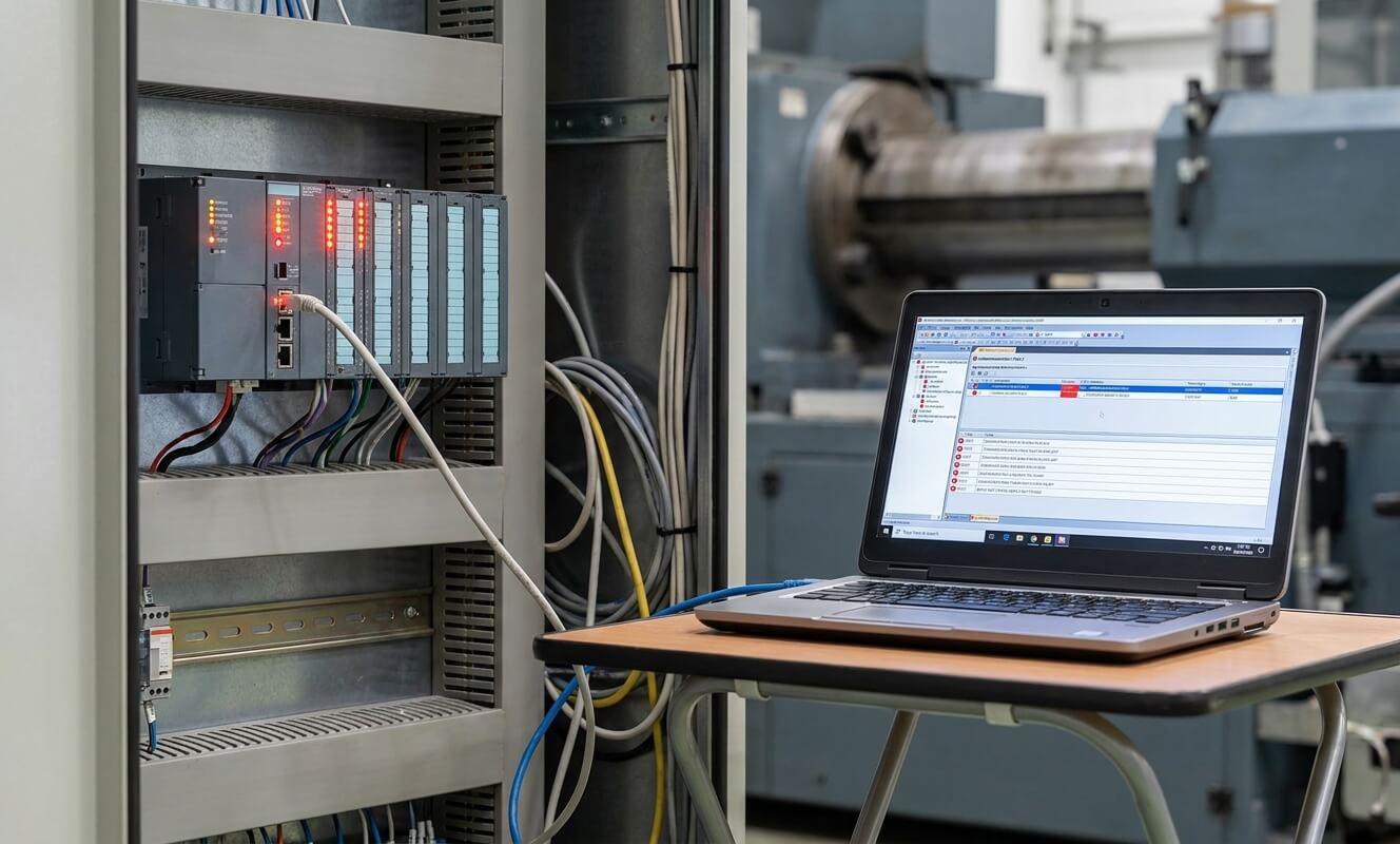
When the network remains unstable after the plant connection, we usually connect a laptop running Wireshark directly into the switch.
Then we monitor:
- ARP traffic
- broadcast frequency
- duplicate IP activity
- excessive multicast traffic
In one factory, we discovered a damaged network camera flooding the switch with ARP packets hundreds of times per second. That traffic overwhelmed the PLC communication network even though the camera itself had nothing to do with the machine.
Without packet monitoring, nobody would have found the problem quickly because the symptoms looked like PLC communication instability instead of network flooding.
The Permanent Solution Is Proper Network Segmentation
One of the biggest commissioning mistakes is treating the industrial control network like a normal office LAN.
Modern automation systems need separation.
That is why we now configure VLAN segmentation much more aggressively on industrial managed switches.
The goal is isolating:
- PLC communication
- HMI traffic
- VFD communication
- SCADA traffic
- office IT traffic
into separate logical environments.
We also enable broadcast storm control directly inside the switch configuration because uncontrolled broadcast traffic can overwhelm industrial devices very quickly.
Once the network becomes segmented properly, communication stability improves dramatically.
Problem #4: Ground Loops Are Creating Communication Chaos
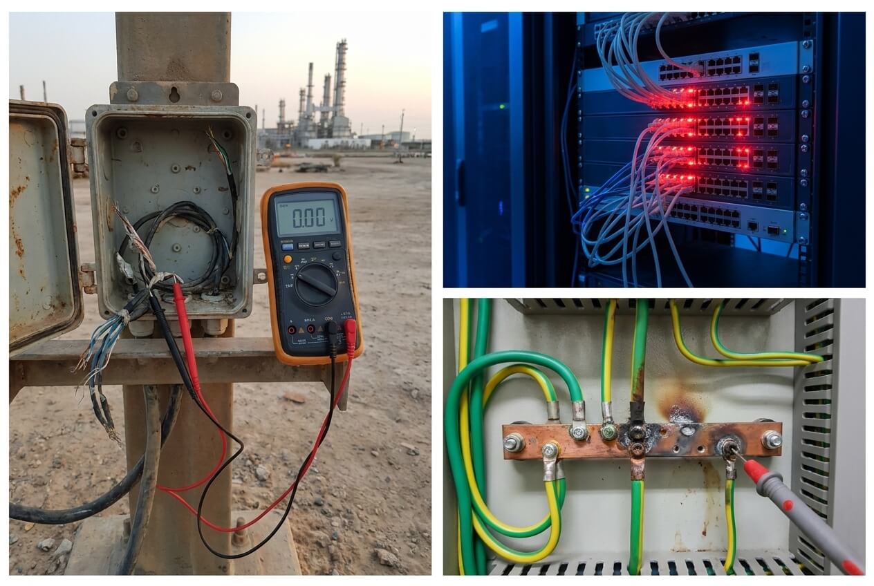
Ground loop problems are some of the most misunderstood communication failures because the symptoms look extremely strange.
Sometimes technicians notice the communication cable shield becoming warm. In severe cases, tiny sparks appear when disconnecting the shield grounding point.
This usually happens on long-distance instrument wiring between remote field devices and the main control panel.
The root problem is ground potential difference.
Different physical locations inside a factory rarely sit at exactly the same electrical ground potential. Once a shield gets connected at both ends across a long distance, electrical current may begin flowing through the shield itself.
At that point, the shield stops behaving like a shield and starts behaving like a conductor.
That creates communication instability very quickly.
What We Do First During Emergency Troubleshooting
The first emergency action is usually disconnecting the shield grounding at the field device end temporarily.
We leave the shield grounded only at the control panel side.
In many situations, this immediately stops the circulating ground current and stabilizes the communication network.
A lot of engineers feel uncomfortable disconnecting one side because they were taught that “more grounding is safer.” In communication systems, improper grounding often creates more problems instead of solving them.
The Long-Term Solution Depends on the Site Requirements
Single-point grounding works well in many installations, but certain environments require dual-end grounding because of high-frequency noise or explosion-proof installation standards.
In those situations, proper equipotential bonding becomes critical.
Instead of allowing the shield itself to carry the current, we install a heavy copper bonding conductor between the two grounding systems so the potential difference equalizes safely through a low-resistance path.
This is one of those areas where theory and real industrial environments often collide. Grounding strategies that work perfectly inside a laboratory do not always survive large industrial facilities with long cable distances and multiple grounding systems interacting together.
The Tools Every Commissioning Engineer Should Carry
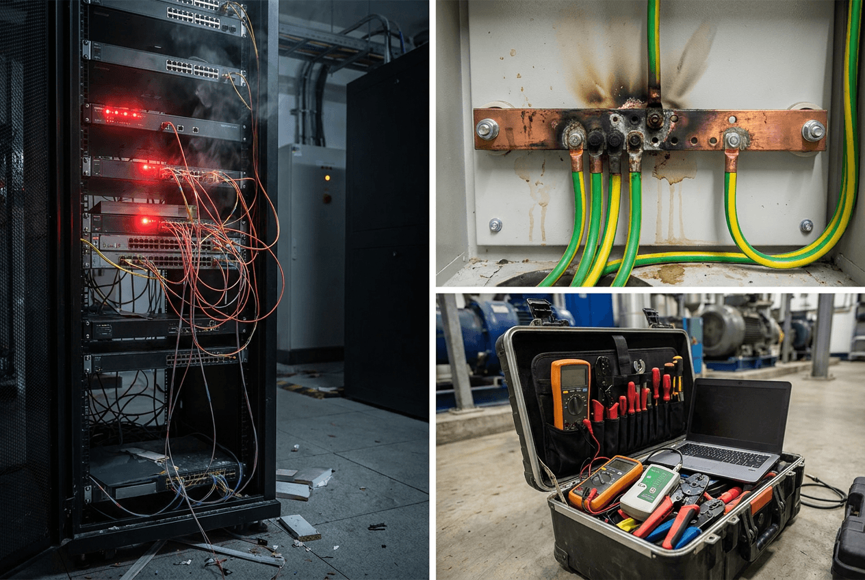
After enough painful startup experiences, most experienced controls engineers end up carrying the same troubleshooting tools everywhere.
The tools are not complicated.
What matters is knowing when to use them.
A small box of 120Ω resistors[⁷] becomes incredibly valuable when diagnosing RS485 reflections[⁸] onsite.
Snap-on ferrite cores[⁹] are useful because they allow quick EMI suppression[¹0] testing without rewiring the entire machine.
A proper multimeter[¹1] and cable tester[¹2] remain essential because many communication problems[¹3] eventually turn out to be physical wiring problems underneath.
A laptop with Wireshark installed has become almost mandatory during Ethernet troubleshooting because guessing network behavior blindly wastes enormous amounts of commissioning time.
USB-to-RS485 adapters also save a huge amount of frustration when direct serial communication testing becomes necessary.
The reality of commissioning work is that speed matters. The faster an engineer can isolate the physical cause of a communication problem, the faster the project moves forward.
Conclusion
Communication failures during commissioning rarely happen because the PLC suddenly “stops working.” Most of the time, the communication system is reacting to physical conditions that were never controlled properly during installation or design.
Electrical noise, poor grounding, bad topology, long cable reflections, and unmanaged network traffic all follow understandable physical behavior once you stop treating communication alarms like random software bugs.
The biggest mistake during commissioning is relying on guesswork and endless rebooting instead of diagnosing the environment logically.
Strong communication systems are not created by luck. They come from disciplined wiring practices, proper grounding strategy, good network architecture, and realistic testing under industrial conditions.
That is why we now perform heavy communication stress testing before shipment on every OEM project we build. We simulate electrical noise, long-distance communication loads, and network congestion conditions before the equipment ever reaches the customer site.
Because once the machine arrives onsite, nobody wants to spend the next week restarting PLCs and hoping the communication problems disappear on their own.
FAQ
Why does PLC communication work in the workshop but fail onsite?
Because the workshop environment is usually much cleaner electrically than the real factory environment.
Once the machine reaches the customer site, the communication system suddenly has to deal with the following:
- VFD noise
- long cable distances
- poor grounding
- shared factory networks
- unstable power quality
A communication system that looks stable during FAT may become unstable immediately after installation if the field environment was never considered properly.
How far should communication cables stay away from VFD power cables?
There is no perfect universal distance, but in most industrial panels, keeping at least 30 cm (12 inches) of separation between communication wiring and high-voltage motor cables is a good starting point.
More separation is usually better.
If the cables must cross, they should cross at 90 degrees instead of running parallel together.
Long parallel cable runs are one of the biggest causes of EMI-related communication problems.
Why does lowering the baud rate sometimes fix communication problems?
Lower baud rates are more tolerant of electrical noise and signal reflections.
At high baud rates, communication signals become more sensitive to:
- cable quality
- grounding problems
- improper termination
- long-distance reflections
Lowering the baud rate slows communication slightly, but it often stabilizes unreliable RS485 or Modbus networks immediately during commissioning.
Should communication cable shields be grounded at one end or both ends?
It depends on the installation environment.
For many industrial control systems, single-point grounding works well because it prevents ground loop current from flowing through the shield.
In high-frequency or special industrial environments, dual-end grounding may still be required, but proper equipotential bonding must exist between the grounding systems.
Improper dual-end grounding is one of the most common causes of communication instability on long cable runs.
What is the fastest way to diagnose an industrial Ethernet problem?
The fastest first step is usually isolation.
Disconnect the machine network from the factory network temporarily and see whether communication stabilizes.
If the PLC and HMI work normally after isolation, the problem is probably coming from the larger plant network instead of the control panel itself.
After that, tools like Wireshark help identify the following:
- broadcast storms
- duplicate IP addresses
- excessive ARP traffic
- damaged network devices
Do ferrite cores really help with PLC communication problems?
Yes, especially in environments with strong VFD noise.
Ferrite cores help absorb high-frequency electrical interference traveling along communication or power cables.
They are not a magic solution for every problem, but during commissioning they are often a fast and effective way to reduce EMI issues without redesigning the entire panel.
What is the biggest communication mistake during commissioning?
The biggest mistake is troubleshooting by guessing.
Many engineers immediately start rebooting PLCs, replacing switches, or changing software settings randomly without understanding the physical cause of the failure.
Most communication problems follow predictable electrical behavior.
Once the real physical cause is identified, the fix is usually much simpler than people expect.
Related Products:
Related Articles: