May 6, 2026PLC & Automation Systems
The Field Engineer’s Guide to Validating PLC Spares
Don’t Just "Plug and Pray": The Field Engineer’s Guide to Validating PLC Spares It’s a scenario every field engineer knows too well: The production line is dead, management is breathing down your neck
Don’t Just "Plug and Pray": The Field Engineer’s Guide to Validating PLC Spares
It’s a scenario every field engineer knows too well: The production line is dead, management is breathing down your neck, and you finally have the replacement PLC module in your hand. But before you slide it into the rack, you face a high-stakes question: Is this module truly ready for service, or are you about to introduce a new set of "mystery" problems?
Installing unverified spares is a leading cause of commissioning delays. At UniRegal, we’ve seen that "New in Box" doesn't always translate to "Ready to Run." This guide provides a field-tested checklist to help you validate PLC components before they hit the live system, moving your team from "hope-based maintenance" to data-driven reliability.
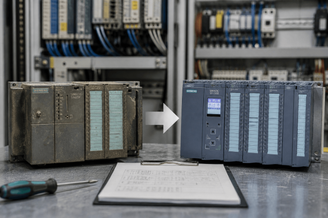
Step 1: Beyond the Label — Verify Hardware Revisions (HW/FS)
It’s easy to glance at a part number and assume it’s a direct swap. However, major families like Siemens S7 or Rockwell ControlLogix evolve through multiple hardware revisions. While the base part number stays the same, a newer revision might handle backplane timing differently or require a different terminal block pinout.
- The Action: Cross-reference the hardware (HW) and functional (FS) versions printed on the module's side label with your system’s "as-built" documentation.
- Expert Tip: If the revision is significantly newer than your existing setup, check the manufacturer’s product lifecycle notes. Sometimes, a newer module requires a software service pack update before the CPU will even recognize it.
Step 2: The Silent Killer — Firmware Compatibility
Firmware mismatch is the #1 reason replacement modules fail on-site. A communication module or CPU with the wrong firmware version might "see" the network but refuse to talk to the HMI, or worse, it might reject your logic download entirely.
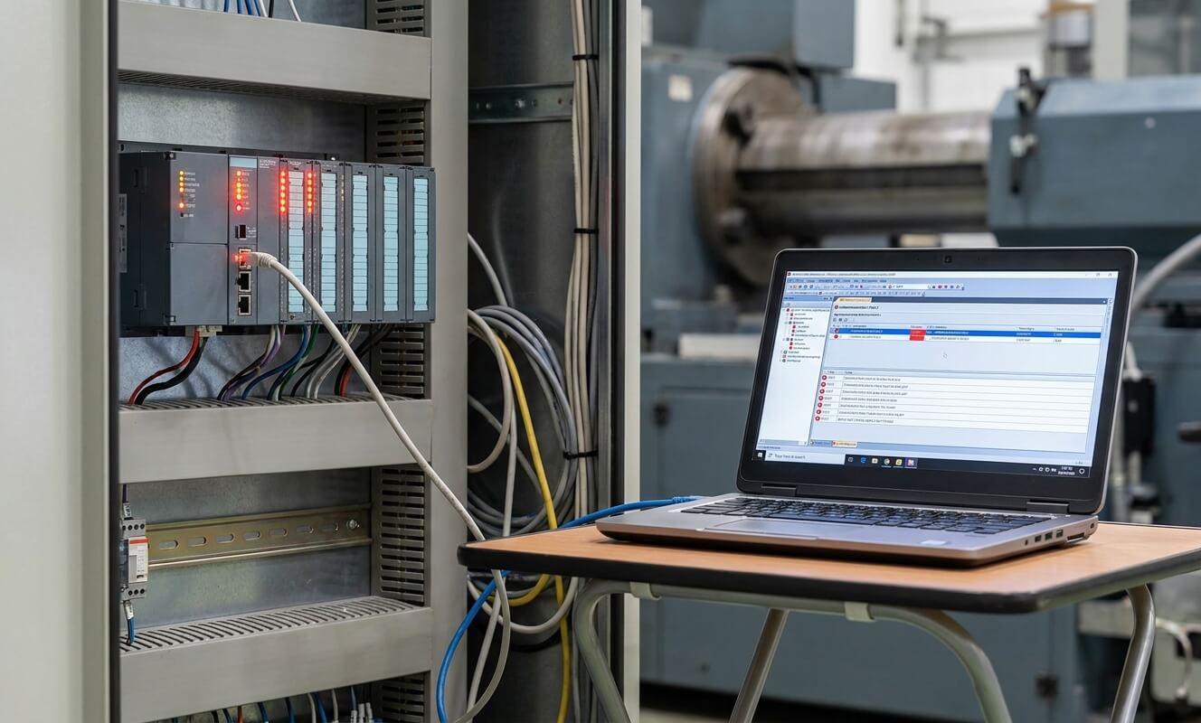
Before you head to the plant floor, connect the module to your engineering workstation (e.g., TIA Portal or Studio 5000) to:
- Read the actual firmware version (don't trust the sticker; it might have been flashed by a previous user).
- Compare it to the offline project configuration.
- The Decision: If they don't match, flash the firmware in your office environment. Never try to update firmware for the first time during an emergency downtime event; the risk of "bricking" the module is too high when you're under pressure.
Step 3: The Power-On and Self-Test (POST) Sequence
Apply power in a safe test environment and watch the LEDs carefully. A solid green "Power" light is a good start, but it’s only 10% of the story.
- Watch for Boot Loops: Does the module stay powered, or does it reset every 30 seconds?
- Identify Red Flags: Look for the "SF" (System Fault) or "Major Fault" indicators. If these don't clear after a few seconds, the module’s internal circuitry might be compromised.
- Note: Passing a power-on test only proves the module isn't "Dead on Arrival" (DOA). It does not guarantee it will execute your specific industrial logic correctly.
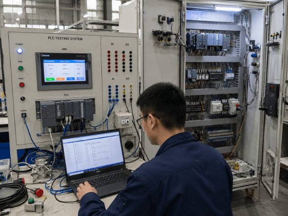
Step 4: Validate Communication and I/O Integrity
A module can look healthy but still have "deaf" communication ports or blown output transistors. If your test bench allows, perform these quick functional checks:
- For Communication Modules: Perform a simple ping test or try to go online with the device. Ensure the response time is stable and there are no "dropped packets."
- For I/O Modules: This is the most ignored step. If possible, force a few I/O points in the software and verify the physical response. For inputs, simulate a signal and ensure the status bit flips in the PLC data table. This prevents the nightmare of "software says it's on, but the valve isn't moving."
Step 5: The "Go/No-Go" Decision
After completing the checklist, you should have a clear verdict. You are safe to install ONLY IF:
- The hardware revision matches your rack's physical and electronic requirements.
- The firmware is synchronized with the rest of your system's ecosystem.
- The communication is stable under a test load.
- The I/O mapping responds accurately without signal "ghosting."
Why This Protocol Matters for Plant SEO (System Efficiency & Optimization)
Skipping these steps might save you 15 minutes during the initial swap, but it often leads to hours of troubleshooting "intermittent" faults later. Mismatched spares create "version drift," where a system works just well enough to pass a shift but fails randomly due to timing issues.
Related Resource: Proper testing starts with proper storage. Learn How to Store PLC Modules to Prevent Component Failure to ensure your spares are ready when you need them.
How UniRegal Simplifies Your Spare Parts Strategy
In high-stakes industrial environments, you need a technical partner, not just a parts vendor. UniRegal supports field engineers by eliminating the guesswork:
- Pre-Shipment Validation: We can verify and flash firmware/hardware revisions before the part even leaves our warehouse.
- Compatibility Consulting: Not sure if a newer revision is backward-compatible with your legacy backplane? Our technical team has the documentation to confirm it for you.
- Hard-to-Find Revisions: We specialize in sourcing exact revision matches for legacy systems, saving you from the headache of forced program upgrades.
Conclusion: Test Before You Stress
The goal of pre-installation testing isn't just to see if a module is "good" or "bad"—it's to ensure total system integration. By following this checklist, you move from "reactive firefighting" to "proactive reliability."
Need help verifying a critical spare?
Contact us today. Send us your model numbers and system configuration, and we’ll help you ensure a successful installation before you take the risk on-site.