Jul 7, 2026Case Studies
How a Packaging Machine OEM Eliminated Repeated Startup Delays
Test PLC spare parts before installation to avoid downtime and system failure. Learn how to verify firmware, communication, and I/O compatibility to ensure reliable operation.
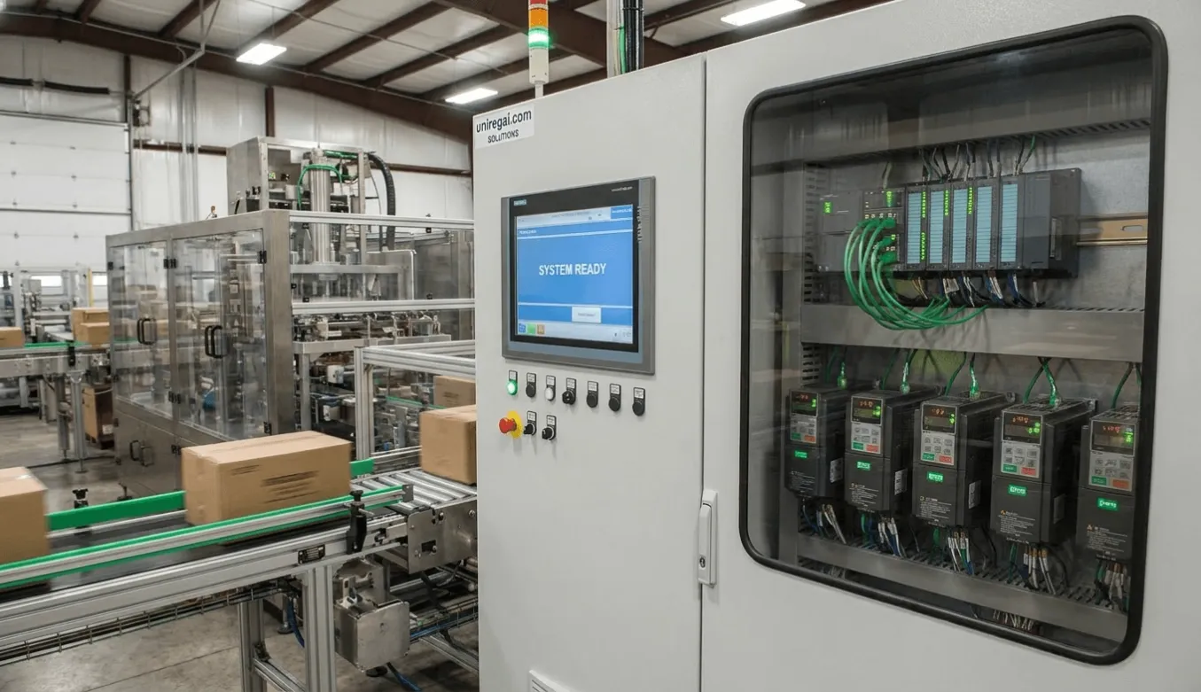
How a Packaging Machine OEM Eliminated Repeated Startup Delays Caused by PLC-VFD Communication Failures
For many packaging machine OEMs, the most dangerous automation problems are not catastrophic failures.
They are the intermittent problems that appear only after the machine arrives at the customer site.
Inside the OEM factory, the equipment may run perfectly for days:
- servo systems synchronize correctly,
- Conveyors operate smoothly.
- HMIs respond normally.
- And PLC-VFD communication appears completely stable.
Then the machine is shipped, installed into a real production environment, connected to the customer’s factory network, and pushed into full-speed operation.
Suddenly, everything changes.
The PLC[^1] begins reporting intermittent communication timeout alarms[^2]. VFD status packets[^3] disappear randomly. High-speed conveyors stop unexpectedly. Operators reset the system repeatedly while commissioning engineers search for faults that seem impossible to reproduce consistently.
The machine itself is not failing mechanically.
What is collapsing is the stability of the automation communication layer under real electromagnetic[^6] conditions.
This case study explains how we helped a packaging machine OEM[^7] eliminate repeated startup delays caused by intermittent PLC-VFD communication failures[^4] by redesigning the electrical architecture around industrial EMC[^5] discipline rather than basic cabinet assembly logic.
The Cost of the “Last-Mile” Startup Failure
The OEM specialized in high-speed packaging systems used in food and consumer goods production environments.
Their machines contained:
- multiple servo axes,
- high-power VFDs,
- Profinet communication networks,
- distributed I/O systems,
- HMIs,
- barcode systems,
- and synchronized conveyor sequencing.
At the factory, FAT testing consistently passed.
But after installation at customer facilities, commissioning repeatedly became unstable once:
- all drives operated simultaneously,
- production motors reached full load,
- and the machine integrated into the customer’s broader plant network.
The PLC intermittently lost communication with multiple VFDs.
Some failures lasted milliseconds. Others triggered watchdog timeouts severe enough to stop the entire packaging line.
The operational consequences escalated quickly:
- startup schedules extended from days into weeks,
- commissioning engineers remained on-site far longer than planned,
- customer production schedules slipped,
- And the OEM’s engineering credibility began coming under pressure.
What made the situation especially difficult was that the failures appeared random.
Sometimes the machine operated normally for hours before communication collapsed unexpectedly.
This type of intermittent automation instability is one of the most difficult categories of industrial troubleshooting because the root cause usually exists below the software layer.
The machines did not have a PLC problem—they had an EMC problem.
After reviewing startup logs, electrical drawings, and field behavior, one pattern became increasingly clear:
The communication failures were not originating from the PLC logic itself.
The deeper issue was electromagnetic interference (EMI) generated by the interaction between:
- high-frequency VFD switching,
- cabinet wiring structure,
- grounding methods,
- and industrial communication architecture.
This distinction mattered enormously.
Because once industrial communication problems become electromagnetic problems, traditional software troubleshooting rarely solves them permanently.
The failures were rooted in the physical behavior of the electrical system itself.
And in modern high-speed packaging machines, that physical layer becomes extremely sensitive because
- VFDs switch at high carrier frequencies.
- Servo systems generate rapid electrical transitions.
- Communication networks operate at high data speeds.
- and machine layouts are often compressed into extremely dense cabinet structures.
At that point, the control cabinet is no longer simply distributing power and signals.
It becomes an electromagnetic environment that must be engineered intentionally.
Root Cause #1 — VFD Power Cables Were Polluting the Communication Network
The first major issue involved cable routing inside the control cabinet and machine structure.
To reduce cabinet size and simplify assembly, the original design routed the following:
- VFD motor output cables,
- Profinet communication cables,
- and low-voltage control wiring
through the same wire duct over extended distances.
From a conventional wiring perspective, the system appeared organized.
Electromagnetically, however, the cabinet had become extremely unstable.
Modern VFDs generate high-frequency switching harmonics through PWM (pulse width modulation) operation. These switching events create strong electromagnetic emissions, especially along motor output cables carrying rapidly changing voltage waveforms.
When high-power motor cables run parallel to industrial Ethernet communication lines, the communication cables begin acting like receiving antennas.
The result is not always immediate communication failure.
More commonly, the electromagnetic noise intermittently corrupts Ethernet data frames during high-load operation.
Under light testing conditions, communication may appear stable.
Under real production loads, however, the system begins experiencing the following:
- packet corruption,
- timeout events,
- intermittent communication loss,
- and unpredictable watchdog trips.
This is exactly why the failures only appeared after full production startup at customer facilities.
Root Cause #2 — The “Pigtail Ground” Was Making the Noise Worse
The second issue involved shielding termination.
After detecting communication instability, field technicians attempted to improve grounding by stripping the communication cable shield and connecting it to ground using small “pigtail” wires attached to nearby terminals.
This is one of the most common EMC mistakes in industrial automation.
At low frequencies, the grounding appeared acceptable.
At high frequencies, however, the pigtail connection created extremely high impedance because of the skin effect behavior of electromagnetic noise.
Instead of allowing high-frequency interference to dissipate effectively, the narrow grounding path restricted noise discharge and actually amplified shielding inefficiency.
In several areas, the grounding structure also unintentionally created ground loop conditions.
Because small voltage potential differences existed between cabinet sections and machine frames, interference currents began circulating through unintended grounding paths.
The communication system was no longer simply receiving external noise.
The machine structure itself had become part of the interference path.
This is one reason why EMC failures are so difficult in packaging automation:
The machine frame, wiring structure, grounding network, and communication architecture all interact as one electromagnetic system.
Root Cause #3 — Signal Reflection Was Corrupting the Bus Network
The third issue emerged inside the RS485 and CAN-based communication segments connecting multiple VFDs.
During factory testing, communication appeared stable because cable lengths were relatively short.
At the customer site, however, the physical installation expanded significantly, increasing total network cable length well beyond the original testing environment.
The problem was that the final VFDs in the daisy-chain communication structure did not have proper 120 Ω termination resistors enabled.
At higher cable lengths, this created signal reflection problems.
High-speed communication pulses traveling along the cable reflected at the open network end similarly to waves reflecting from a hard surface.
Instead of dissipating cleanly, the reflected signals interfered with subsequent communication pulses, gradually corrupting network stability under operating conditions.
Again, the issue did not appear consistently under low-load testing.
It emerged dynamically once the machine operated continuously under real industrial conditions.
Why Intermittent Communication Problems Become So Expensive
One of the reasons OEMs struggle with intermittent automation faults is that they destroy engineering predictability.
A hard failure can usually be diagnosed relatively quickly.
Intermittent communication instability behaves differently.
The machine may:
- run perfectly for several hours,
- fail briefly,
- recover temporarily,
- Then fail again under different operating conditions.
As a result, engineers begin troubleshooting:
- PLC logic,
- software timing,
- network switches,
- sensor behavior,
- and drive parameters simultaneously.
Commissioning becomes increasingly chaotic because nobody fully trusts the system state anymore.
According to Siemens industrial communication guidelines, electromagnetic compatibility failures remain one of the leading hidden causes of unstable industrial network behavior in high-speed automation systems.
In packaging automation, where production synchronization depends on millisecond-level coordination between drives and controllers, communication instability quickly becomes a full operational shutdown risk.
The Remediation Strategy—Rebuilding the Cabinet Around EMC Discipline
Once the root causes were identified, the objective was not simply fixing one communication problem.
The objective was rebuilding the control architecture around industrial-grade EMC principles.
This required changing how the OEM approached the following:
- wiring layout,
- grounding,
- shielding,
- filtering,
- and communication fault tolerance.
Step 1 — Strict Physical Separation Between Power and Signal Wiring
The first change involved restructuring the cabinet wiring topology completely.
High-voltage motor power cables were separated physically from:
- Profinet communication lines,
- encoder feedback cables,
- and low-voltage signal wiring.
Inside the cabinet:
- AC power wiring was routed on one side,
- Communication and control wiring on the opposite side.
Where crossings were unavoidable, cables crossed only at 90-degree angles to minimize electromagnetic coupling.
This dramatically reduced noise induction into communication circuits.
The OEM also established a permanent engineering rule:
Maintain at least 10 cm of physical separation between VFD motor cables and industrial communication wiring wherever possible.
This became part of the company’s future electrical manufacturing standard.
Step 2—Replacing “Pigtails” with 360-Degree Shield Grounding
The second improvement addressed shielding termination.
All pigtail grounding methods were eliminated.
Instead, dedicated EMC shield clamps were installed at:
- cabinet cable entry points,
- VFD connection zones,
- and industrial switch locations.
The braided shield of each communication cable was terminated directly through 360-degree metal-to-metal shield contact.
This created a low-impedance path for high-frequency noise to discharge directly into the grounded cabinet structure.
Unlike narrow pigtail wires, full circumferential shield grounding remains effective against high-frequency EMI generated by modern VFD systems.
This single change significantly improved communication stability under heavy motor loading conditions.
Step 3 — Suppressing Noise at the Source
The third stage focused on reducing electromagnetic emissions directly at the VFD level.
To minimize conducted and radiated noise:
- line reactors were added to large VFD inputs.
- Ferrite cores were installed on motor output cables.
- And additional filtering measures were implemented around high-frequency switching zones.
Rather than attempting to “protect” communication systems from interference afterward, the strategy shifted toward reducing the amount of interference generated in the first place.
This is one of the core principles of industrial EMC engineering:
Controlling noise at the source is always more effective than fighting noise later downstream.
Step 4—Adding Communication Fault Tolerance Inside the PLC Logic
The final improvement involved software-layer resilience.
Previously, even very brief communication interruptions immediately triggered full machine alarms and emergency stop conditions.
This made the system operationally fragile because tiny transient communication disturbances could halt the entire production line.
The PLC watchdog logic was revised to the following:
- allow limited communication retries,
- debounce transient faults,
- and prevent nuisance shutdowns caused by extremely short packet interruptions.
Importantly, this was not used to hide poor electrical design.
It was used to improve operational robustness after the physical EMC problems had already been corrected.
The result was a communication system that behaved much more realistically under industrial operating conditions.
The Result — From Three Weeks of Startup Chaos to Stable Same-Day Commissioning
After implementing the EMC redesign standards across subsequent packaging machine projects, the OEM reported dramatic improvements during field commissioning.
The most important improvement was not simply reduced alarm frequency.
It was restored startup predictability.
Machines that previously required weeks of intermittent troubleshooting now reached stable production operation within hours after installation.
Commissioning engineers no longer spent days chasing random timeout alarms or unexplained communication drops.
Customer confidence improved significantly because the machines behaved consistently under real production loads.
Most importantly, the OEM transformed EMC design from an afterthought into a standardized engineering discipline integrated directly into future control panel manufacturing practices.
Final Thoughts
As packaging automation systems become faster, denser, and more interconnected, industrial communication stability increasingly depends on electrical architecture quality rather than software alone.
In many OEM projects, startup delays are not caused by programming failures.
They are caused by:
- electromagnetic interference,
- poor grounding strategy,
- wiring topology mistakes,
- and communication architectures that were never designed for real industrial EMC conditions.
This is why modern packaging machine control panels require much more than functional wiring.
They require electrical systems engineered around:
- signal integrity,
- electromagnetic behavior,
- grounding discipline,
- and long-term communication stability under production conditions.
Because in high-speed industrial automation, the real challenge is not getting the machine to run once inside the factory.
The real challenge is ensuring it continues running reliably after entering the far more unforgiving electrical environment of the customer’s production floor.