
Sep 21, 2026
Why Your 4–20 mA Loop Reads Wrong on Site (and It Isn't the Transmitter)
A 4–20 mA loop reading low or drifting on site is rarely the transmitter. In the panels we test, it is loop-load headroom, a ground loop, or a 2-wire/3-wire mismatch the bench never reproduced.
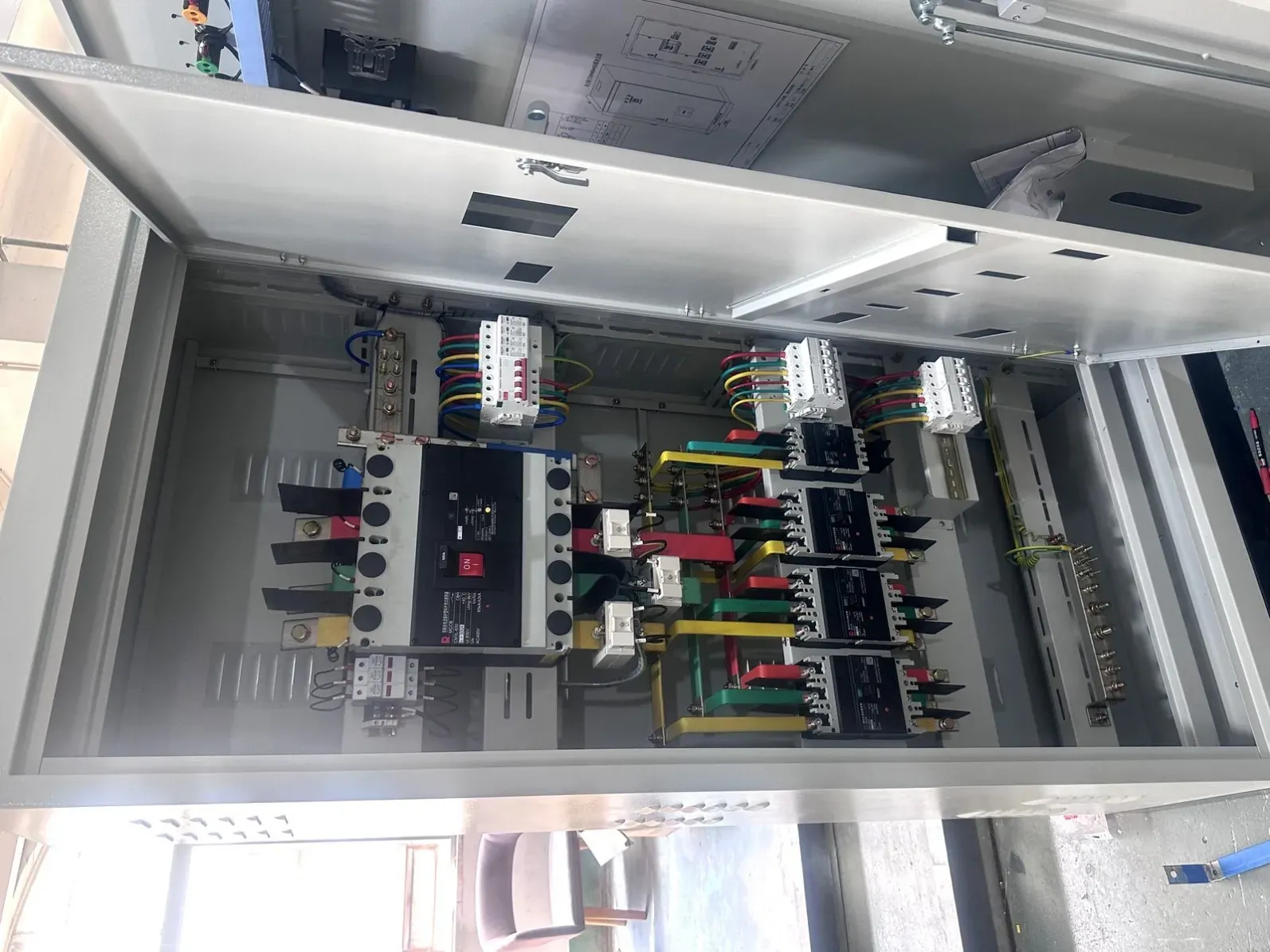
A 4–20 mA analog loop that reads a steady 4.0 mA at zero and 20.0 mA at full scale on the test bench, then reads low, drifts, or throws a fault the moment it is energised in the plant, is almost never a bad transmitter. In the panels we build and test, the failure is one of three field-only conditions: the loop cannot drive enough current once real cable is added, a ground-potential difference between the cabinet and the field device injects common-mode error, or the wiring and scaling on site do not match what was assumed at build. Below is how to tell which — with the numbers that prove it.
Where our scope ends
We build and source control panels, terminate the analog loops, and run Factory Acceptance Test (FAT) on every analog input before shipment. We do not calibrate your field transmitter, program the DCS or SCADA, or carry out on-site commissioning — that stays with your integrator. What we remove is every panel-side cause of a bad reading, and we ship a loop drawing and a measured reference so your site team can close the loop fast.
Cause 1 — The loop is starved under real load
A 2-wire, loop-powered transmitter is fed by a 24 V DC loop supply and must keep itself alive while driving current through everything in series: the cable, the analog input card, and any isolation or intrinsic-safety barrier. The transmitter needs a minimum of roughly 10.5–12 V across its own terminals at 20 mA. That leaves a maximum loop load of about (24 V − 11 V) ÷ 0.020 A ≈ 650 Ω.
A typical PLC or DCS analog input presents 250 Ω (it converts 4–20 mA to a 1–5 V drop the card can read, and that 250 Ω is also what HART needs). Add 500 m of signal cable (a few tens of ohms round trip) plus a 250–500 Ω intrinsic-safety barrier, and you are already near or over the 650 Ω ceiling. At 20 mA the transmitter simply cannot hold the voltage, so the current sags — and the reading reads low even though the transmitter is perfectly good.
Check it: measure the total loop resistance — cable (both ways) + analog input + barrier — for every analog channel, and compare it to (V_supply − V_transmitter_min) ÷ 0.020. Then measure the actual loop current at the field end with a calibrated mA meter at 4, 12 and 20 mA, not at the bench. If the field-end current cannot reach 20.0 mA, the loop is starved, not the sensor. Per NAMUR NE43, a reading below 3.6 mA or above 21.0 mA is a defined fault condition, so a loop that pins at ~3.8 mA is telling you it has run out of drive, not that the transmitter has died.
Cause 2 — The cabinet and the field device sit on different earths
On the bench the transmitter, the panel and the test gear share one ground, so the common-mode voltage between signal common and earth is essentially zero. On site the cabinet is bonded to plant earth while the field device may be hundreds of metres away on a different earth point. That difference appears as common-mode voltage riding on the signal — noise, drift, or a reading that wanders with plant load.
The classic amplifier of this problem is a shield grounded at both ends: the shield becomes a second conductor between two earths and carries the circulating current instead of the signal pair.
Check it: measure the voltage between signal common and true earth at both the panel end and the field end. If there is more than a volt or two between them, ground the shield at one end only, keep the signal pair off earth at the field end, and add a galvanic isolator or an isolated analog input so the signal path is no longer tied to both earths at once.
Cause 3 — The wiring or scaling does not match the installed device
The panel is built and scaled for a 4–20 mA, 2-wire device, but the transmitter that actually gets fitted on site is a 3-wire or 4-wire unit, or the 2-wire loop has been landed with reversed polarity, or the PLC engineering-unit range does not match the transmitter span. On the bench you tested with the device in hand; on site the device — and the drawing — is different. The reading is "wrong" only because the two ends of the loop were never reconciled.
This is also where HART breaks: HART superimposes a 1 mA peak-to-peak digital signal on the 4–20 mA analog. It needs a low loop load (roughly 250–300 Ω) to communicate. A loop that is already near its drive ceiling will read analog fine but refuse to talk to the handheld.
Check it: confirm the transmitter signalling type (2-wire loop-powered vs 3/4-wire separately powered, and whether the loop supply is active or passive) and its calibrated span, then confirm the PLC analog input scaling (raw counts → engineering units). Finally reconcile the loop diagram against the actual terminations, including 2-wire polarity at every loop. A one-page loop drawing beats a point list here.
Quick troubleshooting table
Symptom | Most likely cause | Measurement to confirm |
|---|---|---|
Reads ~3.8 mA at zero, or cannot reach 20 mA | Loop load too high (starved) | Sum R_cable + R_AI + R_barrier; compare to (V_supply − V_tx_min) ÷ 0.020 |
Drifts, noisy, wanders with plant load | Ground loop / common-mode | Measure V between signal common and earth at both ends |
Reads analog but HART will not connect | Loop load too high for HART | HART needs ≈250–300 Ω; check 250 Ω present, reduce extra resistance |
Fixed offset, wrong zero or span | Scaling / span mismatch | Compare PLC engineering units to transmitter span; check 2-wire polarity |
Steady 0 mA or below 3.6 mA | Open loop / no loop power | Verify 24 V present at transmitter; confirm loop supply side |
Our pre-shipment loop checklist
These are the steps we take before a panel with analog I/O leaves the build:
- Loop-load budget — for every analog input, total loop resistance (cable both ways + analog input + barrier) is kept at or below (V_supply − V_transmitter_min) ÷ 0.020.
- Signalling type confirmed — 2-wire, 3-wire or 4-wire, and active or passive loop supply, noted per loop.
- Shield grounded at one end — the signal pair is kept off earth at the field end, and signal cables are routed away from VFD and power cables.
- Isolation where it matters — isolated analog inputs or galvanic isolators specified wherever the field device is remote from the cabinet or bonded to a separate earth.
- Burn-in with a real signal — every analog input is exercised at 4, 12 and 20 mA with a calibrated source, not just a continuity check, and the as-found mA at 0/50/100% is recorded.
- Scaling reconciled — PLC scaling is checked against the transmitter span in the FAT paperwork.
- On-site check sheet — shipped with the expected mA at 0/50/100% so the site team can verify in minutes.
FAQ
My transmitter reads 3.8 mA at zero instead of 4.0 mA. Is the sensor broken? Usually not. A reading that sits just below 4.0 mA is a classic sign the loop cannot quite reach full current — almost always loop-supply headroom or a little too much loop resistance. Check the loop load before you swap the transmitter.
Why does it read perfectly on the bench but drift on site? Because the bench has one ground and short leads. On site, cable resistance and a ground-potential difference between the panel and the field device introduce errors the bench literally cannot reproduce. Ground the shield at one end and isolate where the field device is remote.
What is a safe 4–20 mA loop-resistance budget? For a 2-wire transmitter on a 24 V loop, keep total loop load at or below about 250–300 Ω as a working rule, and never above (24 − 11) ÷ 0.020 ≈ 650 Ω. Longer cable runs and the analog input's own resistance eat into that budget, so calculate it before the build rather than after commissioning.
Does 2-wire versus 4-wire actually matter for my panel? Yes. A 2-wire loop is powered by the loop itself, so the supply must provide enough headroom after cable and input resistance. A 4-wire device has separate power. Landing a 2-wire device into a 4-wire assumption (or reversing its polarity) is a routine cause of a "wrong" reading.
Can HART run on any 4–20 mA loop? Only if the loop load is low enough — roughly 250–300 Ω. A loop already near its drive ceiling will read analog fine but the HART communicator will not connect, because there is no headroom left for the 1 mA digital signal.
What does NAMUR NE43 mean for my loop? NE43 defines the fault band: a current below 3.6 mA or above 21.0 mA signals a wiring or supply fault, not a process value. So a loop pinned at ~3.8 mA is the transmitter telling you it has run out of drive — a loop problem, not a sensor problem.
Do you build panels with isolated analog inputs? On request, and we recommend it wherever the field device is remote from the cabinet or bonded to a different earth. Isolation removes the ground-loop path that causes most site drift.
Talk to us before the build
If your last panel arrived with analog loops that read fine in FAT and then misbehaved on site, send us the loop list, the transmitter types and the enclosure spec. We build and source control panels in enclosures of carbon steel, 304–316 stainless or galvanised, to IP65 or NEMA 4X, with UL-listed facilities sourced per order — panel builds run from an MOQ of 5 units with about a 15-day turn, and component kits dispatch in 3–5 days. We close the loop on load, isolation and scaling before the panel ships. See also our notes on panels that pass FAT but fail on site. Reach us at https://www.uniregal.com/contact.