
Aug 24, 2026Engineering Toolkit
What Should Be Included in a Water Treatment Commissioning Checklist?
A water-treatment commissioning checklist: what to verify before start-up — I/O mapping, enclosures, grounding and documentation — so the system runs on day one.
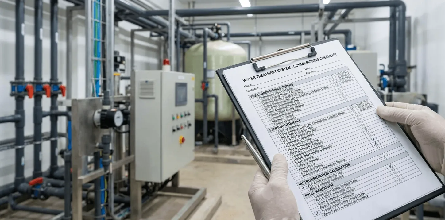
A water treatment commissioning[¹] checklist should verify more than whether pumps can run and treated water can be produced.
It should confirm that the installed system matches the approved design, every control and protection function responds correctly, the treatment process remains stable under realistic operating conditions, and the buyer receives enough documentation[²] and training to operate the plant after the commissioning team leaves.
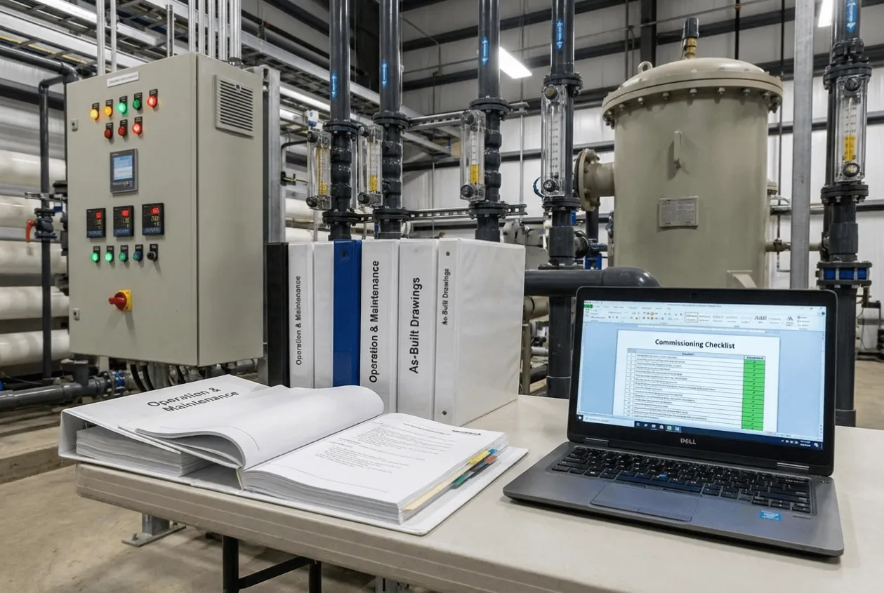
A system is not ready for acceptance simply because it has produced one compliant water sample.
Commissioning is complete only when the mechanical installation, electrical system, automation logic, process performance, safety functions, documentation and operator readiness have all been verified against agreed acceptance criteria[³] and the operating team has received appropriate operator training[⁴].
How to Use This Checklist
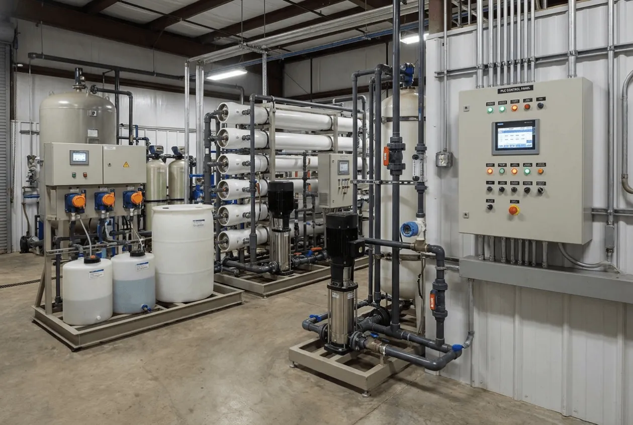
This checklist is designed for industrial water treatment and wastewater treatment projects involving equipment such as:
- Pretreatment systems
- RO and ultrafiltration systems
- Chemical dosing systems
- Filtration and softening systems
- Wastewater treatment plants
- Sludge-handling equipment
- Pump skids
- PLC and HMI control panels
- Online process instrumentation
Not every item will apply to every project. The commissioning team should adapt the checklist to the approved process design, equipment scope and contractual performance requirements.
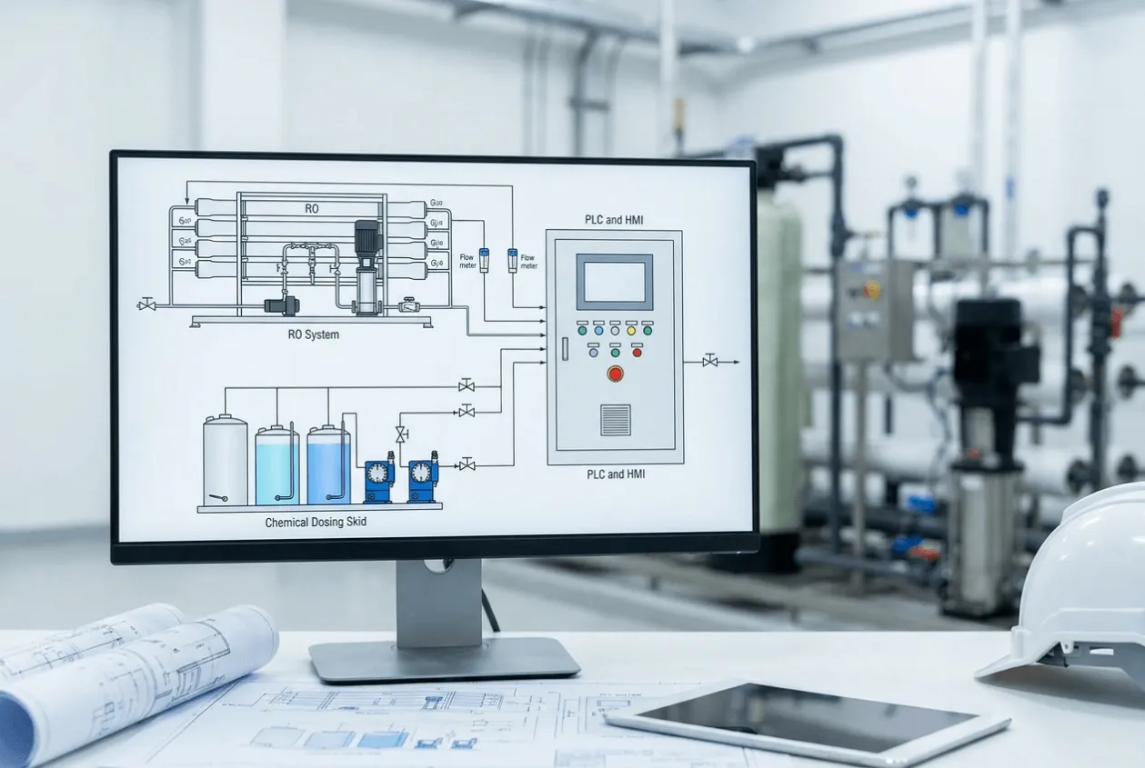
Each item should be marked with one of four statuses:
Status | Meaning |
|---|---|
Accepted | Checked and operating as required |
Accepted with comment | Safe to proceed, but minor correction is required |
Open | Incomplete and recorded on the punch list |
Hold point | Commissioning must not continue until the issue is resolved |
The checklist should also identify who verified each item, the date of verification, the evidence reviewed and any corrective action required.
Stage 1: Confirm the Commissioning Basis
Commissioning should not begin until the project team agrees on what will be tested and what will count as acceptance.
Without a defined commissioning basis, suppliers may demonstrate that equipment can run while the buyer expects proof that the complete process can meet its performance requirement.
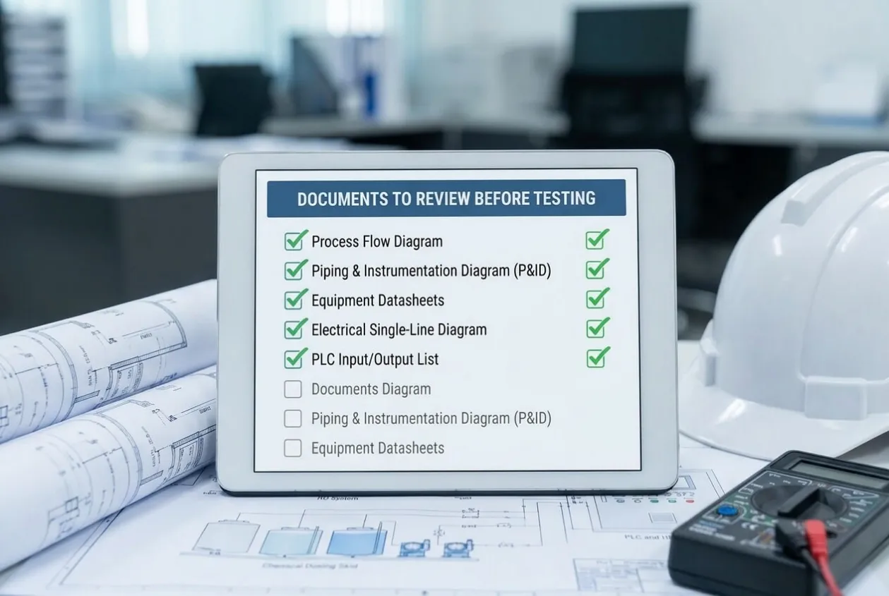
Documents to Review Before Testing
Confirm that the following approved documents are available:
- Process flow diagram
- Piping and instrumentation diagram
- General arrangement drawing
- Equipment datasheets
- Instrument list
- Valve list
- Motor and load schedule
- Electrical single-line diagram
- Control-panel drawings
- PLC input and output list
- Cause-and-effect matrix
- Alarm and interlock list
- Control philosophy
- Chemical dosing calculations
- Utility requirements
- Commissioning procedure
- Performance guarantee
- Approved test methods
- Supplier and buyer responsibility matrix
Any difference between the installed system and the approved documents should be identified before startup.
Buyer RiskCommissioning against outdated drawings can create false acceptance. The equipment may pass the test while the final installation, control logic or operating sequence no longer matches the approved design.
Acceptance Criteria to Define
Before the first test, the commissioning plan should state:
- Required feed-water conditions
- Minimum, normal and maximum operating flow
- Required treated-water quality
- Recovery rate
- Reject or waste flow limits
- Chemical consumption basis
- Energy-consumption basis, where guaranteed
- Minimum stable operating period
- Sampling locations
- Laboratory test method
- Number and frequency of samples
- Allowed instrument tolerance
- Conditions requiring test repetition
- Responsibility for correcting failed tests
The acceptance criteria should be measurable. Statements such as “the system operates normally” are not strong enough for final acceptance.
Stage 2: Verify Site Readiness Before Startup
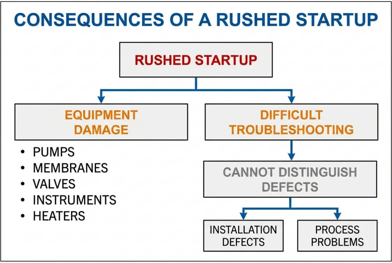
Many commissioning problems begin because the system is started before the installation is ready.
A rushed startup may damage pumps, membranes, valves, instruments, heaters and chemical dosing equipment. It can also make later troubleshooting difficult because the team cannot distinguish between installation defects and process problems.
Civil and Structural Readiness
Confirm that:
- Equipment foundations are complete
- Anchor bolts are tightened
- Platforms and access stairs are secure
- Equipment supports are installed correctly
- Bunds and chemical-containment areas are complete
- Floors drain toward the correct collection point
- Overflow routes are unobstructed
- Maintenance access is available
- Membranes, filters and pumps can be removed without structural interference
- Equipment labels and area identification are installed
- Lighting and ventilation are sufficient
- Outdoor equipment is protected against expected environmental conditions
The installation should not be accepted if routine maintenance requires unsafe lifting, blocked access or dismantling unrelated equipment.
Utility Readiness
Confirm that all required utilities are available and within specification:
- Electrical voltage
- Electrical frequency
- Phase sequence
- Instrument air pressure and quality
- Service water pressure
- Flushing-water supply
- Feed-water availability
- Drainage capacity
- Chemical supply
- Heating or cooling utilities
- Communication network
- Emergency power, where required
Utility values should be measured rather than assumed.
A pump may appear faulty when the actual problem is insufficient inlet pressure. A control panel may trip repeatedly because the site voltage is unstable. Commissioning should separate utility limitations from equipment defects.
Stage 3: Mechanical Completion Checklist
Mechanical completion confirms that the installed equipment is safe and ready for dry and wet testing.
It does not prove that the process will perform correctly, but process testing should not begin before mechanical defects have been resolved.
Tanks and Vessels
Verify that:
- Tanks are clean internally
- Construction debris has been removed
- Tank materials match the approved specification
- Inlet, outlet, drain and overflow connections are correct
- Level instruments are installed at the correct elevations
- Manways and inspection openings are accessible
- Vents are installed and unobstructed
- Supports and restraints are complete
- Internal coatings are free from visible damage
- Chemical tanks have suitable secondary containment
- Overflow and drain paths lead to safe locations
Pumps and Rotating Equipment
Verify that:
- Pump model and materials match the approved datasheet
- Pump alignment is acceptable
- Couplings and guards are installed
- Lubrication has been completed
- Rotation direction is correct
- Suction and discharge valves are in the correct position
- Suction lines are free from air traps where applicable
- Strainers are clean
- Flexible connections are installed correctly
- Pumps are primed before wet operation
- Minimum-flow requirements are understood
- Duty and standby equipment is identified correctly
- Vibration and noise remain within acceptable limits
A motor rotating correctly does not prove that the pump is operating at the correct hydraulic point. Flow, pressure and current should also be checked during wet testing.
Piping and Valves
Verify that:
- Pipe materials and ratings match the approved specification
- Pipework is adequately supported
- Flange bolts are tightened
- Gaskets are installed correctly
- Drain and vent points are accessible
- Flow direction is marked
- Valves are tagged
- Manual valves operate through their full range
- Actuated valves move to the correct commanded positions
- Check valves are installed in the correct direction
- Sampling points are accessible
- Chemical injection points are correctly located
- Flushing and cleaning connections are available
- Pressure tests and leak tests have been completed
- Temporary construction strainers and blinds have been removed where required
Filters and Membranes
Verify that:
- Filter elements are the correct grade
- Media type and quantity match the design
- Media has been loaded correctly
- Distribution systems are installed correctly
- Cartridge filters are seated and sealed
- Membrane model and quantity are correct
- Membrane installation direction is correct
- Pressure-vessel end caps are secured
- Preservation chemicals have been flushed according to the supplier’s instructions
- Membranes have not been exposed to prohibited chemicals or temperatures
- Backwash, rinse and clean-in-place connections are complete
Stage 4: Electrical and Control-Panel Checklist
Electrical commissioning should confirm both electrical safety and functional control.
Energizing a panel and seeing the HMI screen turn on is not evidence that the automation system is ready.
Electrical Inspection
Verify that:
- Control-panel construction matches approved drawings
- Incoming supply voltage is correct
- Phase sequence is correct
- Protective devices have the correct ratings
- Earth connections are complete
- Cable glands are installed correctly
- Power and signal wiring are separated where required
- Terminal numbers match the drawings
- Field-device cables are labelled
- Motor insulation tests are complete
- Control-circuit voltage is correct
- Panel heaters and ventilation operate correctly
- Enclosure protection has not been compromised during installation
- Emergency-stop circuits are hardwired where required
- Safety relays or protective circuits have been tested
- Spare terminals and cable entries are sealed appropriately
Motor and Equipment Testing
Test each motor-driven device individually in manual mode before automatic sequences begin.
Confirm:
- Correct equipment identification
- Correct rotation
- Start and stop from the panel
- Start and stop from the HMI
- Local and remote mode operation
- Motor-current reading
- Overload protection
- Fault feedback
- Running feedback
- Emergency-stop response
- Restart behaviour after a power interruption
- Duty and standby selection
- VFD minimum and maximum speed limits
- Feedback scaling for speed-controlled equipment
Manual testing should prove that each device can operate safely on its own. It does not replace testing the equipment within the complete process sequence.
Stage 5: Instrumentation and Calibration Checklist
A water treatment control system can only respond correctly when its measurements are reliable.
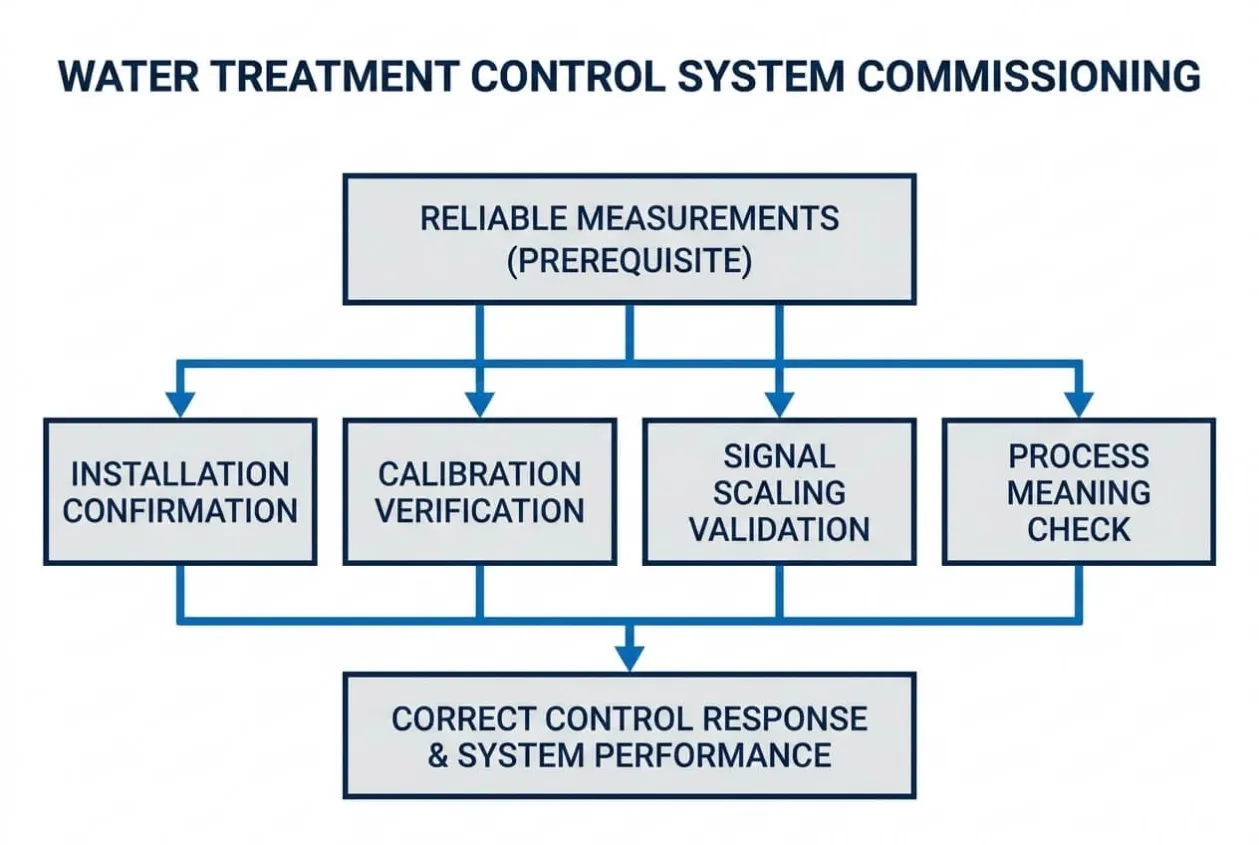
Commissioning should confirm installation, calibration, signal scaling and process meaning.
Instrument Installation
Verify that each instrument:
- Matches the approved tag number
- Matches the specified model and range
- Is installed at the correct location
- Has the correct flow direction
- Is accessible for calibration and maintenance
- Has suitable isolation valves where required
- Is protected from vibration, flooding or chemical exposure
- Has adequate straight pipe length where required
- Is installed at a representative sampling location
- Uses compatible wetted materials
Calibration and Signal Verification
Confirm:
- Calibration certificates are available
- Calibration dates are current
- Zero and span checks have been completed
- Local readings match PLC and HMI values
- Engineering units are correct
- Display resolution is appropriate
- Alarm thresholds are correctly entered
- Signal-failure values are handled correctly
- High-high and low-low limits have been tested
- Analogue scaling is correct across the operating range
- Communication loss generates the intended alarm
- Sensor-cleaning and maintenance requirements are documented
The team should not verify only whether a signal changes.
It should verify whether the signal gives the control system meaningful information.
For example, an online pH analyser may be calibrated correctly but still provide poor control if it is installed before complete chemical mixing. Commissioning should confirm both instrument accuracy and process suitability.
Stage 6: Chemical Dosing System Checklist
Chemical dosing systems should be tested as complete control loops, not only as individual pumps.
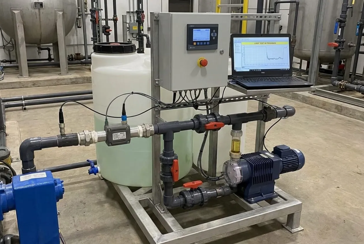
Mechanical and Safety Checks
Confirm:
- Chemical tanks are labelled
- Chemical materials match the design
- Bund capacity is adequate
- Tank vents are installed
- Fill connections are accessible
- Drain points lead to safe collection
- Dosing-pump materials are compatible
- Suction and discharge lines are correctly routed
- Calibration columns are installed where required
- Injection quills and back-pressure valves are installed correctly
- Pulsation dampeners are charged correctly where applicable
- Eyewash and emergency shower facilities are available where required
- Safety Data Sheets are available
- Chemical-handling procedures are understood by operators
Functional Checks
Verify:
- Pump priming
- Actual dosing rate
- Calibration over the expected operating range
- Minimum stable pump output
- Manual dosing control
- Automatic dosing control
- Tank low-level alarm
- Tank low-low trip
- No-flow or loss-of-prime detection
- Duty and standby changeover
- Flow-paced dosing calculation
- Feedback-control response
- Maximum dosing limits
- Chemical dosing inhibition when process flow stops
- Response to analyser failure
- Recovery after a power interruption
A dosing pump can run correctly while the process receives the wrong amount of chemical. Commissioning should therefore verify the complete relationship between measurement, PLC calculation, pump output, mixing and process response.
Stage 7: PLC, HMI and Automatic Sequence Testing
Automatic operation should begin only after field devices have passed individual manual tests.

The commissioning team should test normal operation, abnormal operation and recovery behaviour.
Operating Modes
Confirm that:
- Manual mode works as intended
- Automatic mode works as intended
- Local and remote control are clearly indicated
- Mode changes do not create unsafe equipment movement
- Operators understand which commands have priority
- Maintenance mode is controlled appropriately
- Unauthorized users cannot change critical settings
Startup Sequence
Verify that the automatic startup sequence:
- Checks all required permissives
- Confirms tank levels
- Confirms valve positions
- Confirms utility availability
- Starts equipment in the correct order
- Includes required delays
- Prevents dry running
- Prevents dead-heading
- Prevents chemical dosing without process flow
- Stops the sequence when a critical condition is missing
- Identifies the failed step clearly on the HMI
Shutdown Sequence
Confirm that shutdown:
- Stops dosing at the correct stage
- Maintains flushing where required
- Stops pumps in a safe order
- Returns valves to the correct position
- Prevents backflow or uncontrolled drainage
- Maintains essential equipment where required
- Records the reason for shutdown
- Allows safe restart after the fault is cleared
Alarm and Interlock Testing
The following functions should be tested where applicable:
- Low tank level
- High tank level
- Pump dry-run protection
- High discharge pressure
- Low process flow
- Filter differential-pressure alarm
- Membrane high-pressure shutdown
- High conductivity alarm
- pH high and low alarms
- Chemical tank low level
- Instrument signal failure
- Motor overload
- VFD fault
- Valve-failure alarm
- Communication loss
- Emergency stop
- Control-power failure
- Main-power failure
- Duty-equipment failure
- Standby-equipment start
- PLC restart
- HMI restart
- SCADA communication failure
Testing should confirm more than whether an alarm appears.
The team should verify:
- What equipment stops
- What equipment remains running
- Whether the process moves to a safe condition
- Whether standby equipment starts
- Whether the operator receives a clear message
- Whether the alarm must be acknowledged
- Whether restart is manual or automatic
- Whether the event is recorded in the alarm history
Engineering ReviewA useful alarm should help the operator answer three questions: What happened, what did the system do, and what must be checked before restart? An alarm list containing only tag numbers and generic fault messages does not provide enough operating guidance.
Stage 8: Dry Testing
Dry testing confirms the control logic without introducing process water or chemicals where possible.
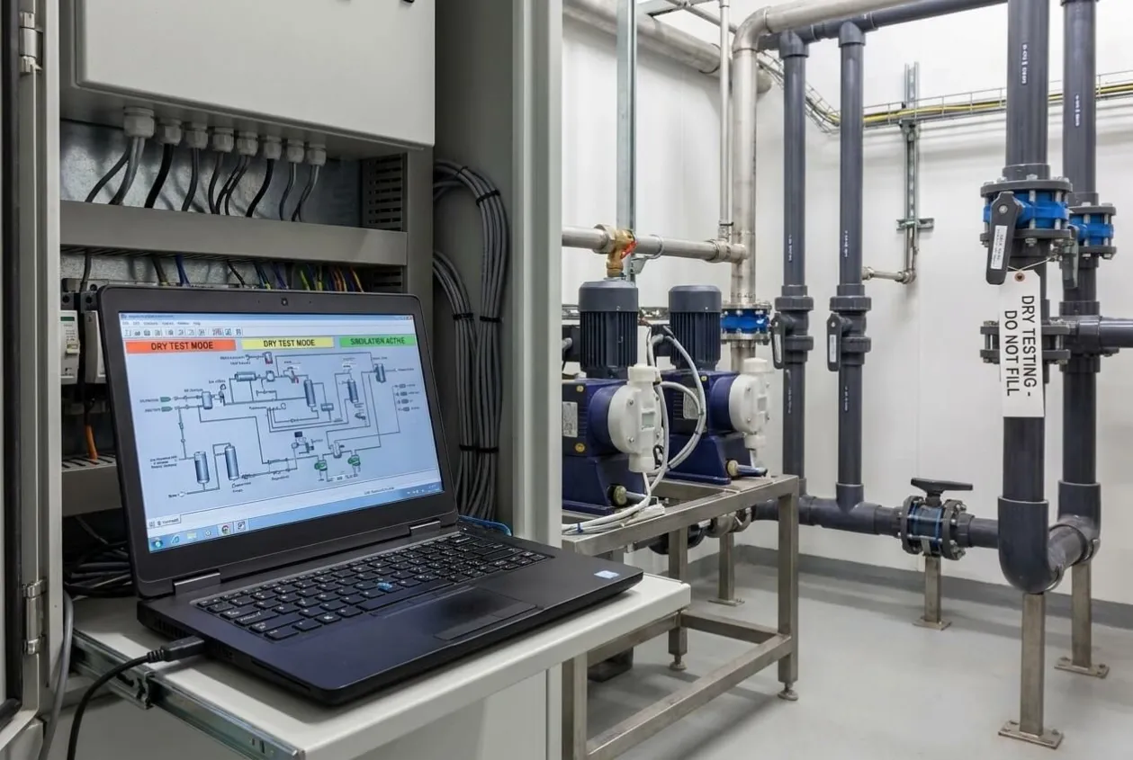
This stage reduces the risk of discovering wiring, sequence or valve-position errors after the plant has already been filled.
Dry testing may include:
- Simulating level signals
- Simulating pressure switches
- Simulating flow signals
- Testing valve feedback
- Testing permissives
- Testing alarm thresholds
- Testing duty and standby logic
- Testing emergency stops
- Testing power-failure recovery
- Testing SCADA communication
- Confirming timer settings
- Confirming HMI status displays
- Confirming equipment naming
- Confirming trend screens
- Confirming operator access levels
All simulated signals should be returned to normal service before wet testing begins.
Stage 9: Wet Testing
Wet testing confirms that the mechanical, electrical and automation systems operate together with water in the process.
Initial wet testing should use clean water where practical before process chemicals or untreated wastewater are introduced.
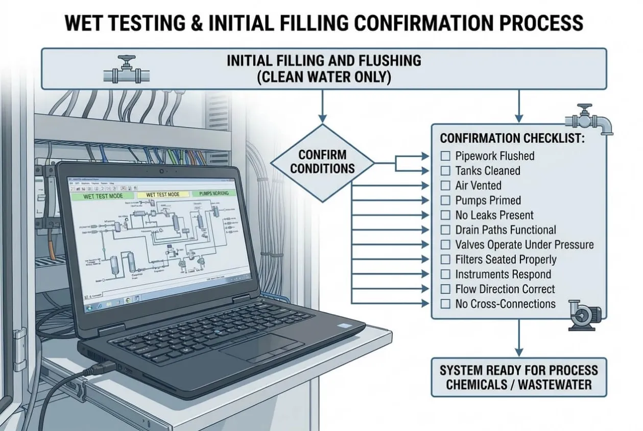
Initial Filling and Flushing
Confirm:
- Pipework has been flushed
- Tanks have been cleaned
- Air has been vented from the system
- Pumps are primed
- No leaks are present
- Drain paths are functional
- Valves operate correctly under pressure
- Filters are seated properly
- Instruments respond to actual process conditions
- Flow direction is correct
- No unexpected cross-connections exist
Hydraulic Testing
Record:
- Feed flow
- Treated-water flow
- Reject flow
- Recirculation flow
- Pump suction pressure
- Pump discharge pressure
- Filter differential pressure
- Membrane pressure
- Tank fill and drain times
- Motor current
- VFD speed
- Valve operating time
These values should be compared with the expected design range.
Unexpected pressure, flow or current should be investigated before performance testing continues.
Stage 10: Process Commissioning
Process commissioning begins when the actual feed water, chemicals, treatment media and operating conditions are introduced.
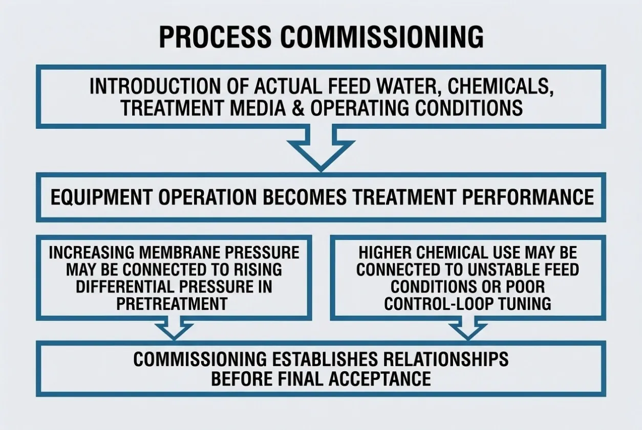
This is the stage at which equipment operation becomes treatment performance.
Process Parameters to Verify
Depending on the system, record and review:
- Raw-water quality
- Feed flow
- Treated-water flow
- Recovery rate
- Reject flow
- pH
- ORP
- Conductivity
- Turbidity
- Total dissolved solids
- Dissolved oxygen
- Differential pressure
- Chemical dosage
- Chemical consumption
- Sludge production
- Filter-cycle duration
- Backwash frequency
- Membrane flux
- Salt rejection
- Biological process indicators
- Discharge-water quality
- Energy consumption
The readings should be reviewed as a connected process rather than as independent values.
For example, increasing membrane pressure may be connected to rising differential pressure in pretreatment. Higher chemical use may be connected to unstable feed conditions or poor control-loop tuning. Commissioning should establish these relationships before final acceptance.
Stage 11: Performance Verification
Producing treated water once is not enough to prove that the system is operationally ready.
Performance verification should demonstrate that the plant can maintain the required result for an agreed period under defined operating conditions.
Performance Test Checklist
Confirm:
- Feed-water conditions remain within the agreed design range
- Required treatment capacity is achieved
- Treated-water quality meets the agreed standard
- Recovery rate meets the requirement
- Chemical dosing remains stable
- Process pressures remain within limits
- Equipment operates without repeated faults
- Automatic sequences work without manual intervention beyond normal duties
- Standby equipment operates correctly
- Alarm and protection functions remain active
- Consumable use is reasonable
- Waste and sludge routes function correctly
- Operator actions are recorded
- Test samples are taken from approved locations
- Laboratory results are traceable
- Deviations are documented
Test Duration
The required test duration depends on the process.
A packaged reverse osmosis (RO) system[⁵] may reach stable operating conditions relatively quickly, although membrane performance still needs to be evaluated under representative feed conditions.
A biological wastewater treatment[⁶] process may require a much longer stabilization period because biomass development and changing loads cannot be evaluated in a few hours.
The commissioning plan should therefore define duration according to process behaviour rather than use one standard period for every system, following recognized water industry commissioning practices[⁷].
Buyer RiskA short demonstration can prove that equipment runs. It may not prove that the treatment process remains stable when inlet conditions change, equipment changes over from duty to standby, or operators take control after the commissioning engineer leaves.
Stage 12: Establish the Operating Baseline
Commissioning data should become the plant’s first operating baseline.
Without baseline data, future operators may notice that performance has changed but have no reliable reference for identifying when or why deterioration began.
The baseline should include:
- Normal flow range
- Normal pressure range
- Filter differential pressure
- Membrane operating pressure
- Pump current
- VFD speed
- Tank cycle times
- Chemical dosing rate
- Chemical consumption
- Conductivity
- pH
- Turbidity
- Recovery rate
- Reject flow
- Cleaning frequency
- Backwash frequency
- Normal alarm status
- Instrument calibration values
- Treated-water quality
The baseline should be recorded under known operating conditions and included in the final commissioning report.
Trends are often more useful than isolated values. The HMI or SCADA system should retain the process variables needed to identify gradual changes where this is part of the project scope.
Stage 13: Operator Training and Readiness
A system should not be accepted as operationally ready if the buyer’s operating team cannot run it safely.
Training should use the installed system rather than rely only on classroom slides or equipment manuals.
Operators Should Be Able to Demonstrate
- Normal startup
- Normal shutdown
- Manual and automatic mode selection
- Alarm acknowledgement
- Response to low tank level
- Response to pump failure
- Response to instrument failure
- Duty and standby changeover
- Chemical refill procedure
- Basic dosing adjustment
- Filter replacement
- Backwash operation
- Membrane flushing
- Routine sampling
- Basic trend review
- Emergency shutdown
- Safe isolation before maintenance
Training should also explain what operators should not adjust without engineering approval.
Setpoints, dosing limits, alarm thresholds and protection delays may appear easy to change from the HMI, but incorrect changes can affect safety or treatment performance.
Maintenance Team Readiness
The maintenance team should understand:
- Equipment isolation
- Lockout and tagout points
- Motor and pump maintenance
- Instrument calibration
- Valve maintenance
- Filter and membrane replacement
- Control-panel access
- PLC and HMI backup
- Fault-history review
- Recommended spare parts
- Escalation route for technical support
Attendance records and training materials should be included in the handover package.
Stage 14: Documentation and Handover Checklist
The final documentation should represent the system that was actually installed and commissioned.
Draft drawings and preliminary manuals are not sufficient for long-term operation.
Required Handover Documents
The final package should include:
- Approved design basis
- Final process flow diagram
- As-built piping and instrumentation diagram
- As-built general arrangement drawing
- Final equipment list
- Equipment datasheets
- As-built electrical drawings
- Panel layout drawings
- Terminal diagrams
- Cable schedule
- Motor list
- Instrument list
- Calibration certificates
- Valve list
- PLC input and output list
- Control philosophy
- Cause-and-effect matrix
- Alarm and interlock list
- PLC program backup
- HMI program backup
- VFD parameter backup
- Network configuration
- Operating manual
- Maintenance manual
- Preventive maintenance schedule
- Chemical Safety Data Sheets
- Consumables list
- Recommended spare-parts list
- Warranty documents
- Commissioning report
- Performance-test results
- Training records
- Open-items list
- Technical-support contacts
Program backups should be usable, clearly labelled and matched to the final commissioned version.
A backup file with no version record or hardware configuration may provide little value when the plant needs it later.
Stage 15: Punch List and Open-Item Control
Not every minor issue must delay the complete project, but every unresolved issue should be documented.
A commissioning punch list should include:
Required Record | Purpose |
|---|---|
Item number | Provides traceability |
Description | Defines the issue clearly |
System or equipment tag | Identifies the affected area |
Priority | Shows whether the item blocks operation |
Responsible party | Prevents unclear ownership |
Required corrective action | Defines what must be completed |
Target date | Controls closure |
Verification method | Shows how completion will be confirmed |
Closure approval | Records buyer acceptance |
Punch-list items should be classified by risk.
Category A: Acceptance Hold Point
The system should not be accepted or operated until the issue is resolved.
Examples include:
- Failed safety interlock
- Unstable treated-water quality
- Incorrect pump rotation
- Serious leakage
- Missing emergency stop
- Incorrect chemical compatibility
- Unverified performance guarantee
Category B: Operational Correction
The system can operate under controlled conditions, but the issue affects reliability or maintainability.
Examples include:
- Incomplete alarm text
- Missing trend display
- Incorrect equipment label
- Minor valve-access problem
- Incomplete spare-parts delivery
Category C: Documentation or Finish Item
The issue does not prevent safe operation but must be closed before final contractual completion.
Examples include:
- Drawing revision
- Final document formatting
- Minor paint repair
- Missing identification plate
The buyer should not sign unconditional final acceptance while critical punch-list items remain open.
Stage 16: Final Acceptance Review
Before signing the final commissioning or acceptance certificate, the buyer should confirm that five questions can be answered clearly.
1. Is the system safe?
Safety devices, emergency stops, chemical-handling arrangements and protective interlocks have been tested.
2. Does the complete process operate automatically?
Equipment does not merely run individually. Startup, shutdown, fault response and recovery have been verified as complete sequences.
3. Does the system meet the agreed performance?
Capacity, treated-water quality, recovery and other guarantees have been demonstrated under the agreed test conditions.
4. Can the buyer operate and maintain it?
Operators and maintenance personnel have completed practical training and received the required documentation, backups and spare-parts information.
5. Are all remaining issues controlled?
Open items have written responsibilities, completion dates and acceptance conditions.
When one of these questions cannot be answered, commissioning may not yet be complete.
Common Commissioning Mistakes Buyers Should Avoid
Accepting the System After One Good Sample
One compliant sample confirms only the condition at the time it was taken. It does not prove stable operation, reliable automatic control or consistent performance under changing load.
Testing Only Normal Operation
Systems often appear reliable while everything is healthy. Commissioning should also test instrument failure, pump failure, high pressure, low flow, low chemical level, communication loss and power interruption.
Leaving PLC Logic Untested
A PLC program may contain all required functions on paper but still respond incorrectly because of field-signal polarity, timer settings, incomplete permissives or incorrect equipment feedback.
Treating Operator Training as a Presentation
Operators need to demonstrate startup, shutdown, fault response and routine maintenance on the actual system.
Signing Before the Documentation Is Complete
After final payment and demobilization, drawings, program backups and calibration records may become more difficult to obtain. Handover requirements should be treated as part of commissioning, not as later administration.
Accepting Undefined Technical Support
“Remote support available” does not define response time, scope, duration, responsibility or cost. Post-commissioning support should be documented clearly.
Water Treatment Commissioning Acceptance Framework
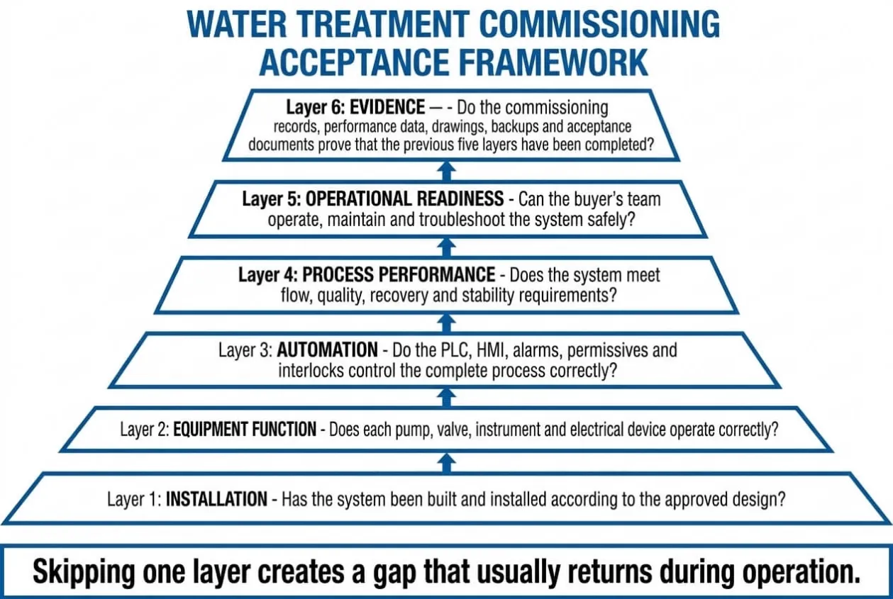
A practical acceptance decision can be made in six layers:
Layer 1: Installation
Has the system been built and installed according to the approved design?
Layer 2: Equipment Function
Does each pump, valve, instrument and electrical device operate correctly?
Layer 3: Automation
Do the PLC, HMI, alarms, permissives and interlocks control the complete process correctly?
Layer 4: Process Performance
Does the system meet flow, quality, recovery and stability requirements?
Layer 5: Operational Readiness
Can the buyer’s team operate, maintain and troubleshoot the system safely?
Layer 6: Evidence
Do the commissioning records, performance data, drawings, backups and acceptance documents prove that the previous five layers have been completed?
Skipping one layer creates a gap that usually returns during operation.
Commissioning Lessons Learned
Mechanical completion is not operational readiness
A system can be fully installed while still being unable to run safely or maintain stable treatment performance.
Every interlock should be tested through its real consequence
Seeing an alarm on the HMI is not enough. The team should verify the resulting equipment response and restart conditions.
Baseline data is one of the most valuable commissioning outputs
Future maintenance teams need normal operating values to identify deterioration early.
Commissioning responsibility should be agreed before the purchase order
Responsibility becomes harder to negotiate after installation problems appear.
Operators should participate before final acceptance
The commissioning engineer should not be the only person capable of running the system correctly.
Documentation should reflect the commissioned system
An accurate as-built package is part of the operating asset, not an optional administrative extra.
Engineering Takeaway
A water treatment commissioning checklist should prove that the complete system is ready to be operated and accepted, not merely that individual equipment can run.
The buyer should verify installation quality, electrical safety, instrumentation, PLC logic, abnormal-condition response, treatment performance, operating baseline, documentation and operator readiness before signing final acceptance.
The most important commissioning question is not:
Did the system produce water today?
It is:
Can the buyer operate this system safely, consistently and independently after the commissioning team leaves?
Need an Independent Review Before Water Treatment Acceptance?
A system can pass a short startup demonstration while still carrying unresolved risks in its PLC logic, alarm strategy, instrumentation, commissioning scope or operating documentation.
Uniregal can review the control and automation side of your water treatment commissioning package before final acceptance.
Send us your:
- P&ID
- Control philosophy
- PLC input and output list
- Alarm and interlock list
- Control-panel drawings
- Commissioning checklist
- Punch list
- Performance-test report
We will help your engineering and purchasing teams identify missing tests, unclear responsibilities and control risks before the final acceptance certificate is signed.
Request a Water Treatment Commissioning Review
The purpose is not to repeat your supplier’s startup work. It is to verify whether the controls, instruments, operating logic and acceptance evidence are strong enough to support reliable operation after handover.
Related Articles:
Commissioning a water-treatment panel? We supply panels with pre-verified I/O and grounding, built by Foshan suppliers to your spec. Talk to our team about your project.SP System