Jul 6, 2026Case Studies
How We Reduced Commissioning Risk in a Complex Water Treatment Panel Project
How We Reduced Commissioning Risk in a Complex Water Treatment Panel Project Water treatment commissioning failures rarely happen because the PLC hardware is defective. Most failures happen because c

How We Reduced Commissioning Risk in a Complex Water Treatment Panel Project
Water treatment commissioning failures rarely happen because the PLC hardware is defective. Most failures happen because critical problems stay hidden until startup day. I have seen projects lose entire weeks because of one incorrectly scaled analog signal or one untested interlock.
In this project, we reduced commissioning risk by shifting debugging work from the jobsite into the factory through full IO simulation, interlock stress testing, communication fault validation, and collaborative FAT procedures.
This was not a small system. The project involved:
- Reverse Osmosis (RO) skids
- Ultrafiltration units
- Chemical dosing systems
- More than 350 IO points
- Multiple Modbus VFD networks
- Differential pressure PID loops
- Remote SCADA integration
The customer had a hard startup deadline because the treatment system was directly connected to plant production. Delays were not acceptable.
That changed how we approached commissioning from the very beginning.
Why Water Treatment Commissioning Becomes High Risk

Water treatment systems are difficult to commission because electrical systems, process equipment, instrumentation, and chemical sequences all depend on each other.
A PLC program may work perfectly in simulation while the real system still fails during startup.
The real problems usually happen here
Commissioning Problem | Typical Root Cause | Real-World Impact |
|---|---|---|
Pumps trip during startup | Incorrect interlock timing | Startup delays |
Unstable PID loops | Bad analog scaling | Pressure fluctuations |
VFD communication loss | Modbus timeout mismatch | Process interruption |
False tank alarms | Sensor noise | Operator confusion |
Chemical overdosing | Incorrect flow feedback | Water quality issues |
In this project, the biggest concern was not programming complexity. It was uncertainty.
The customer had previously experienced a failed startup on another project because field wiring and PLC logic were tested at the same time during commissioning. Every new issue created another chain reaction.
For example:
- instrumentation teams blamed electricians,
- electricians blamed programmers,
- programmers waited for mechanical completion,
- Production schedules continued slipping.
We wanted to avoid that completely.
The Biggest Mistake in Traditional Commissioning
Many panel builders still use a reactive commissioning model.
The workflow usually looks like this:
- Build the panel
- Power it on
- Verify basic IO
- Ship it
- Solve problems onsite
That approach pushes risk directly onto the customer.
Why onsite debugging becomes expensive very quickly
Problem | Hidden Cost |
|---|---|
PLC logic changes onsite | Extended commissioning labor |
Rewiring analog signals | Electrical rework |
Incorrect VFD parameters | Pump instability |
Emergency travel support | Additional project cost |
Startup delays | Production downtime |
In water treatment projects, onsite debugging becomes even more dangerous because many systems cannot be fully tested until water is flowing through live process lines.
That means mistakes happen under real operating conditions.
Not in a safe workshop.
Our First Strategy: Full Analog Signal Simulation Before Shipment

The first major change we made was simple:
We refused to treat FAT as a basic power-on test.
Instead, we simulated actual process conditions inside the workshop.
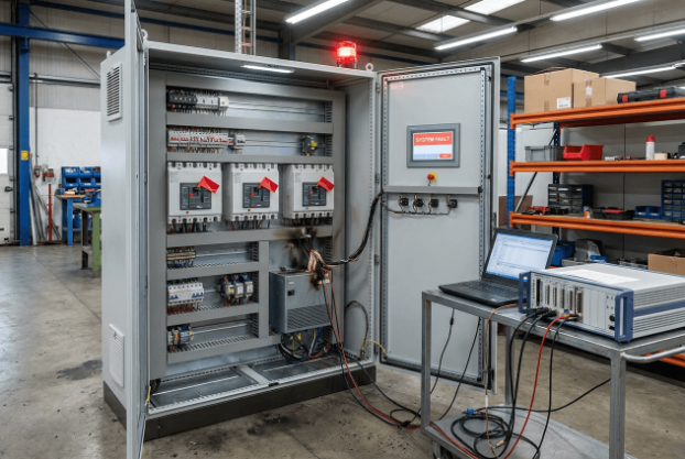
Every critical analog signal was injected directly into the PLC system before shipment using calibrated process simulation equipment.
How we performed analog simulation testing
We used a calibrated Fluke process calibrator to inject simulated 4–20mA signals into the PLC analog input cards.
We simulated:
- RO feed pressure transmitters
- Tank level transmitters
- pH analyzers
- Flow meters
- Conductivity sensors
This allowed us to validate the following:
- analog scaling,
- alarm thresholds,
- PID behavior,
- SCADA trends,
- and interlock responses
before the real field devices even arrived onsite.
The problem we discovered during simulation testing
One RO feed pressure transmitter was incorrectly scaled inside the PLC.
What we expected
Signal Type | Engineering Range |
|---|---|
4–20mA | 0–16 bar |
What the PLC actually used
Signal Type | Engineering Range |
|---|---|
4–20mA | 0–10 bar |
At first glance, the system looked normal.
The pressure values changed correctly.
The pump started correctly.
No alarms appeared.
But during PID simulation testing, we noticed unstable pressure behavior during speed ramp-up.
The PLC believed pressure was rising much faster than reality because the analog scaling was compressed into the wrong engineering range.
That caused:
- unstable PID correction,
- aggressive VFD response,
- and oscillating pump speed commands.
If this issue had reached the field, operators would probably have blamed the following:
- VFD tuning,
- pump sizing,
- or pipe hydraulics.
In reality, the root cause was analog scaling.
That single FAT discovery probably saved multiple commissioning days.
Why We Simulated Fault Conditions Instead of Only Normal Operation

Many FAT procedures only test whether equipment works under normal conditions.
That is not enough.
Real commissioning failures happen during abnormal conditions.
So we intentionally forced failures into the system.
Our goal was not simply to prove the system worked. Our goal was to verify how the system behaved when things went wrong.
Example: High-High Pressure Interlock Validation
The RO skid included a high-pressure protection sequence designed to prevent membrane damage and pipe rupture.
Required shutdown sequence
When pressure exceeded the high-high threshold, the PLC needed to do the following:
- Stop the RO feed pump
- Close the inlet valve
- Generate a SCADA alarm
- Prevent automatic restart
- Require manual operator reset
We simulated the fault condition directly through the analog simulator.
What we discovered
The interlock worked correctly.
But the restart timer logic contained a hidden sequencing problem.
Under one timing condition, the PLC could briefly allow a restart command before the operator completed the manual reset sequence.
The issue only appeared during rapid pressure fluctuation conditions.
Normal FAT testing would never have caught it.
Why this mattered
Without correction, the system could potentially
- restart the RO feed pump unexpectedly,
- create pressure spikes,
- and damage membrane housings.
We corrected the ladder logic before shipment.
That single test justified the entire simulation process.
Our Most Valuable FAT Test: Communication Failure Recovery
Most FAT procedures verify communication startup.
Very few tests communicate failure recovery.
That is a major mistake.
In real facilities, communication networks fail all the time.
Especially in water treatment plants with:
- long cable runs,
- high electrical noise,
- multiple VFDs,
- and remote IO stations.
How we tested Modbus communication failure
The PLC communicated with multiple VFDs over Modbus TCP.
Instead of only confirming communication status, we intentionally disconnected the network during operation.
We wanted to verify:
- alarm generation,
- fail-safe behavior,
- timeout recovery,
- and operator visibility.
The problem we found
One VFD remained in its last commanded speed state after communication loss.
That meant:
- the PLC believed the pump had stopped,
- But the drive continued operating.
This happened because the VFD communication timeout parameter was disabled by default.
Why this issue becomes dangerous on-site
Without timeout protection:
- pumps may continue running without supervision,
- pressure conditions may become unstable,
- and operators may receive misleading SCADA information.
We corrected the timeout behavior before shipment and validated fail-safe shutdown during repeated communication interruption tests.
This became one of the most valuable FAT findings in the entire project.
Why Interlock Validation Matters More Than Most Teams Realize
Most startup failures are not caused by PLC code syntax errors.
They happen because real equipment dependencies were never tested together.
Critical interlocks we validated
Interlock Function | Why It Matters |
|---|---|
Pump dry-run protection | Prevent seal failure |
Tank low-level shutdown | Protect dosing pumps |
Valve permissive logic | Prevent dead-head pressure |
VFD fault shutdown | Prevent sequence conflicts |
E-Stop validation | Personnel safety |
We also validated the physical E-Stop circuit independently from PLC software logic.
According to IEC 60204-1 and NFPA 79 guidelines, emergency stop functions should not rely exclusively on software execution.
Source:
IEC 60204-1 — Safety of Machinery Electrical Equipment
NFPA 79 — Electrical Standard for Industrial Machinery
The FAT Procedure That Actually Reduced Startup Risk
One major reason FAT procedures fail is lack of customer visibility.
Customers often do not see real system behavior until equipment arrives onsite.
We changed that.
Our collaborative FAT process included
- Live video testing
- Shared FAT checklist review
- Real-time SCADA monitoring
- Alarm verification
- Remote customer participation
- Sequence-by-sequence walkthroughs
Every critical sequence required customer approval before shipment.
FAT Checklist Items We Consider Mandatory
FAT Item | What We Verified |
|---|---|
Analog scaling | Correct engineering units |
Alarm thresholds | Proper trigger points |
VFD communication timeout | Safe fail-state behavior |
Valve feedback logic | Correct timeout alarms |
PID response | Stable process control |
Power recovery testing | Controlled restart behavior |
This level of FAT testing takes more effort.
But it dramatically reduces startup uncertainty.
The Real Result: What Reduced Commissioning Risk Looked Like
The biggest success was not simply faster commissioning.
The real success was predictable startup behavior.
Traditional commissioning vs our approach
Metric | Traditional Method | Our Process |
|---|---|---|
Onsite IO debugging | 3–5 days | Less than 1 day |
PLC logic changes onsite | Frequent | Minimal |
Emergency troubleshooting | Common | Rare |
Change orders | High probability | Significantly reduced |
Startup delays | Often unavoidable | None during startup |
The customer specifically told us this was the smoothest water treatment startup they had experienced in years.
That feedback mattered more than any KPI.
Lessons Engineers Can Apply to Their Own Projects

This project reinforced several important commissioning lessons.
1. Never trust analog scaling without simulation
Many scaling problems look normal during basic testing.
Always inject real simulated values and verify.
- PLC scaling,
- SCADA scaling,
- alarm thresholds,
- and PID response behavior.
2. Always test communication failure behavior
Most teams test startup communication.
Very few tests communicate loss recovery.
That is where dangerous failures usually appear.
3. Interlocks should be tested under fault conditions
Do not only test “healthy” sequences.
Force:
- sensor failures,
- valve timeout conditions,
- communication loss,
- and emergency shutdown events.
That is where commissioning risk actually lives.
4. FAT should validate operational behavior, not just wiring
Basic power-on checks are not enough for modern water treatment systems.
A proper FAT should validate the following:
- sequence timing,
- fail-safe response,
- process logic,
- and abnormal condition handling.
FAQ
- What is the difference between FAT and SAT for PLC panels?
FAT (Factory Acceptance Testing) is performed before shipment at the manufacturer's facility. It validates hardware, communication, PLC logic, alarms, and process simulation.
SAT (Site Acceptance Testing) happens onsite after installation. It validates real-world field integration and operational startup under actual process conditions.
- Why is analog signal simulation important during FAT?
Analog simulation allows engineers to validate:
- scaling accuracy,
- PID response,
- alarm behavior,
- and SCADA trends
before field instrumentation is installed.
Without simulation testing, many hidden commissioning problems remain undetected until startup.
- Why should communication loss testing be included in FAT?
Communication failures happen frequently in industrial environments.
Testing communication loss behavior verifies:
- fail-safe operation,
- timeout handling,
- alarm generation,
- and controlled equipment shutdown.
This prevents dangerous uncontrolled operation during network failures.
Conclusion
Reducing commissioning risk in water treatment automation requires more than functional PLC code. Real reliability comes from simulation-driven FAT procedures, aggressive fault-condition testing, validated interlocks, and engineering teams willing to uncover failures before the equipment ever reaches the jobsite.