Jul 15, 2026Case Studies
Why a 690 V VFD Was Considered for a 6.6 kV ID Fan Retrofit
A 560 kW, 6.6 kV ID fan retrofit using a 690 V VFD with step-down/step-up transformers focused on maintainability and spare strategy and verified by a 24-hour load trial.
Why a 690 V VFD Was Considered for a 6.6 kV ID Fan Retrofit
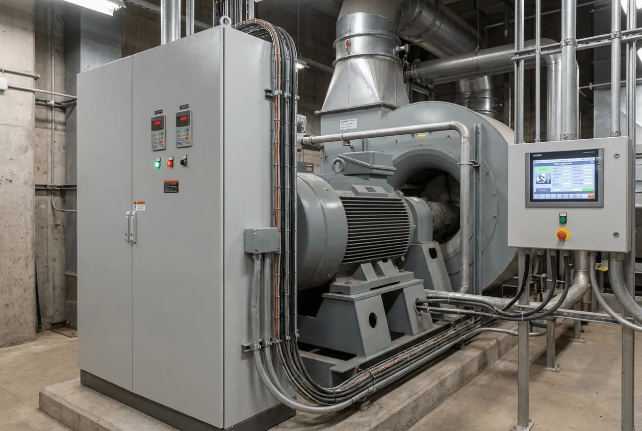
The unusual part of this retrofit was not the 560 kW rating. It was the decision to consider a 690 V low-voltage VFD with transformers for a 6.6 kV ID fan motor. The real question was not only whether the fan could run. It was whether the plant could recover faster when the next drive problem happened.
Project Snapshot
Item | Description |
|---|---|
Industry | Industrial Boiler / Utility System |
Application | Induced Draft Fan control |
Project Type | High-power VFD retrofit and commissioning |
Location | Confidential |
Motor Rating | 560 kW |
Motor Voltage | 6.6 kV |
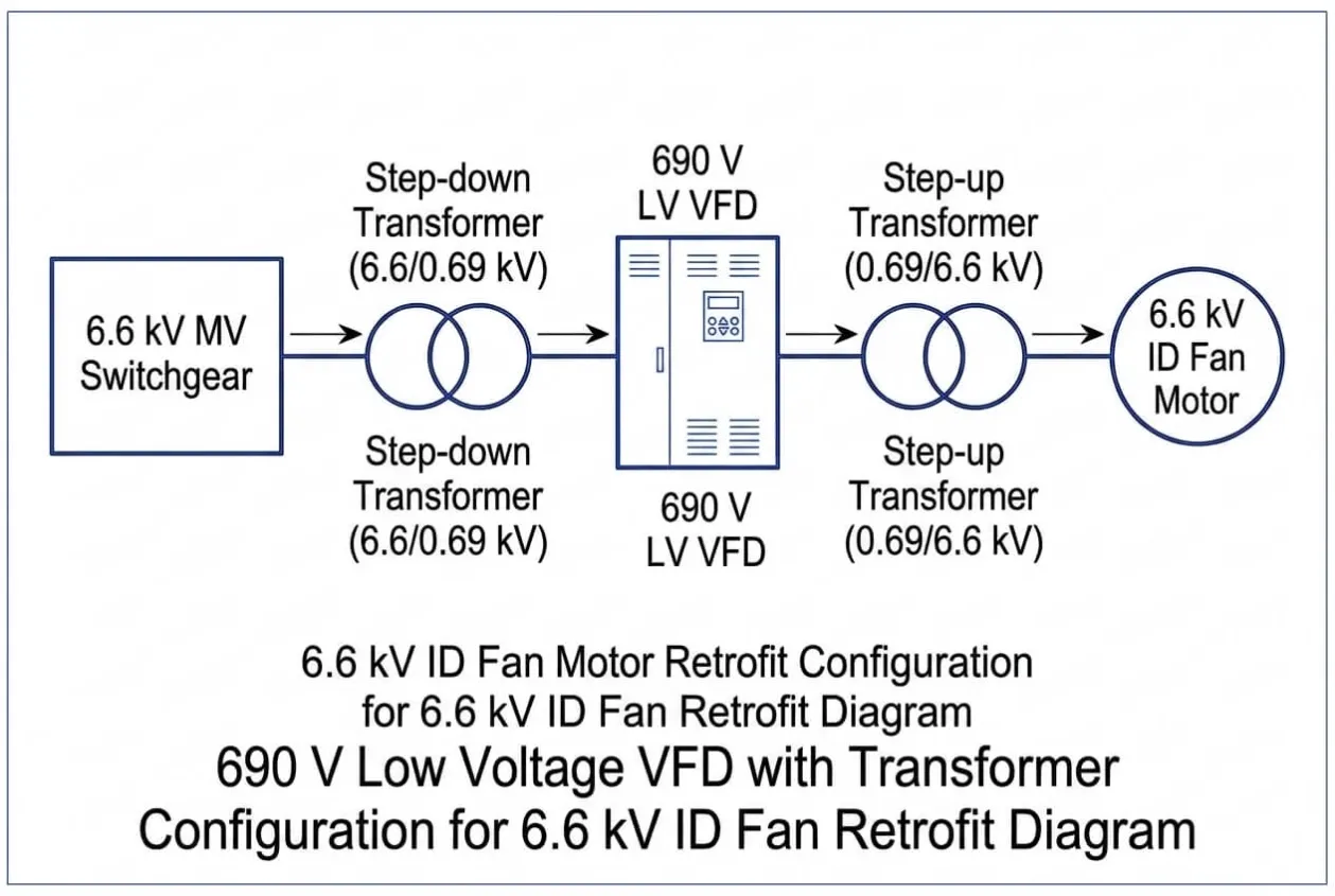
Drive Architecture | 690 V low-voltage VFD with step-down and step-up transformer configuration |
Services | Retrofit review, transformer integration check, VFD parameter setup, PLC I/O verification, protection testing, no-load and load trial commissioning |
Result | Successful commissioning followed by a 24-hour continuous load trial |
Project Overview
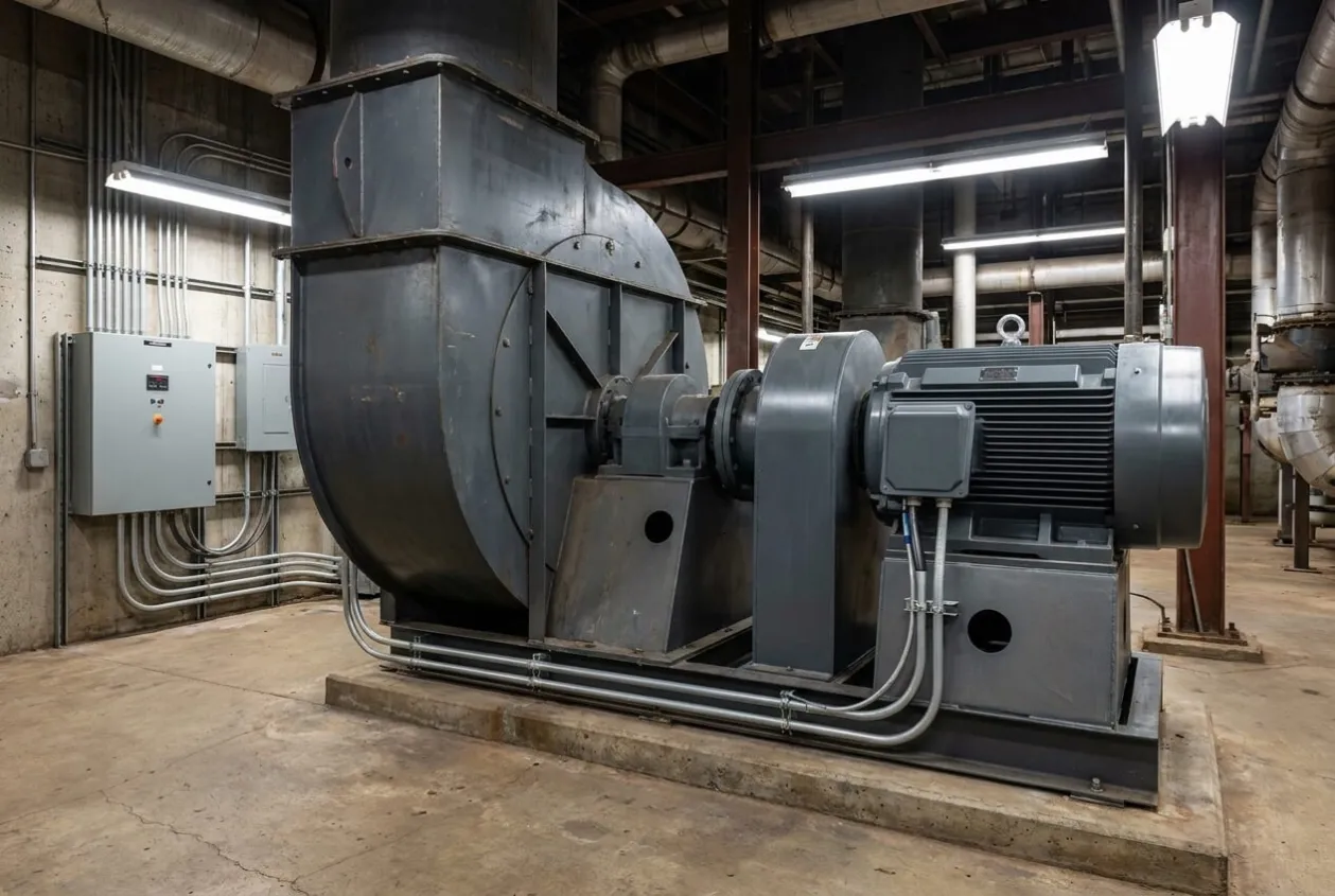
This project involved the retrofit and commissioning of a 560 kW VFD system for a 6.6 kV induced draft fan used in an industrial boiler application.
The existing drive had already served the plant for many years. It was not a failed cabinet waiting to be removed, which made the decision more difficult. When a drive has completely failed, replacement is urgent and easy to explain. When it still runs but becomes harder to support, the discussion becomes more uncomfortable.
That was the real problem.
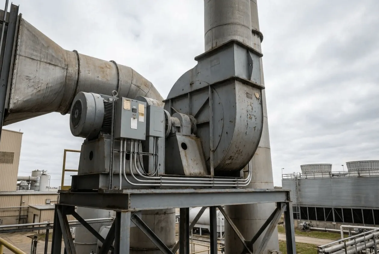
The ID fan was part of the boiler draft system, so the plant could not treat it as a simple motor load. If the fan became unstable, the boiler team would feel it through draft control, combustion stability, and operating confidence. The customer needed modernization, but they also needed to avoid creating a new maintenance problem.
At the beginning, the expected answer was clear: a 6.6 kV motor should use a medium voltage VFD.
But after reviewing spare-part availability, maintenance capability, support risk, and future downtime recovery, the engineering discussion changed. The question was no longer “Which voltage should we use?” It became “Which system will the plant still be able to maintain five years from now?”
That shift became the foundation of the retrofit.
Customer Challenge
From the customer’s perspective, the old drive created a quiet but serious risk.
The plant was not dealing with a dramatic failure. The fan was still running, and daily operation continued. But the maintenance team already understood the situation. Spare parts were becoming harder to plan. Support for the old platform was less predictable. The next failure could take longer to recover from than the plant was comfortable with.
This is a common buyer trigger in VFD retrofit projects. The equipment has not failed yet, but the risk has already moved from technical inconvenience to operational exposure.
The customer needed to answer several practical questions before approving the retrofit:
- Can the existing 6.6 kV motor remain in service?
- Is a medium voltage VFD the only realistic option?
- Will a new drive reduce future downtime, or only replace the old problem with a new one?
- Can the maintenance team support the selected platform without depending on long spare lead times?
- Will transformer integration create hidden commissioning risks?
- Can the fan prove stable under real boiler load?
The most painful concern was not the first startup. It was the next fault.
A drive that starts successfully during commissioning is not enough. The plant needed a solution that would be easier to maintain after handover. If a power section failed later, the team needed a clearer recovery path. If troubleshooting was required, the platform had to be practical for the people who would actually maintain it.
This is where engineering can reduce buyer risk. The work is not only to select a drive but also to help the customer avoid a retrofit decision that looks correct on paper and becomes difficult in operation.
Engineering Review
The engineering review focused on whether a low-voltage VFD with transformer configuration could be a practical solution for a 6.6 kV ID fan motor.
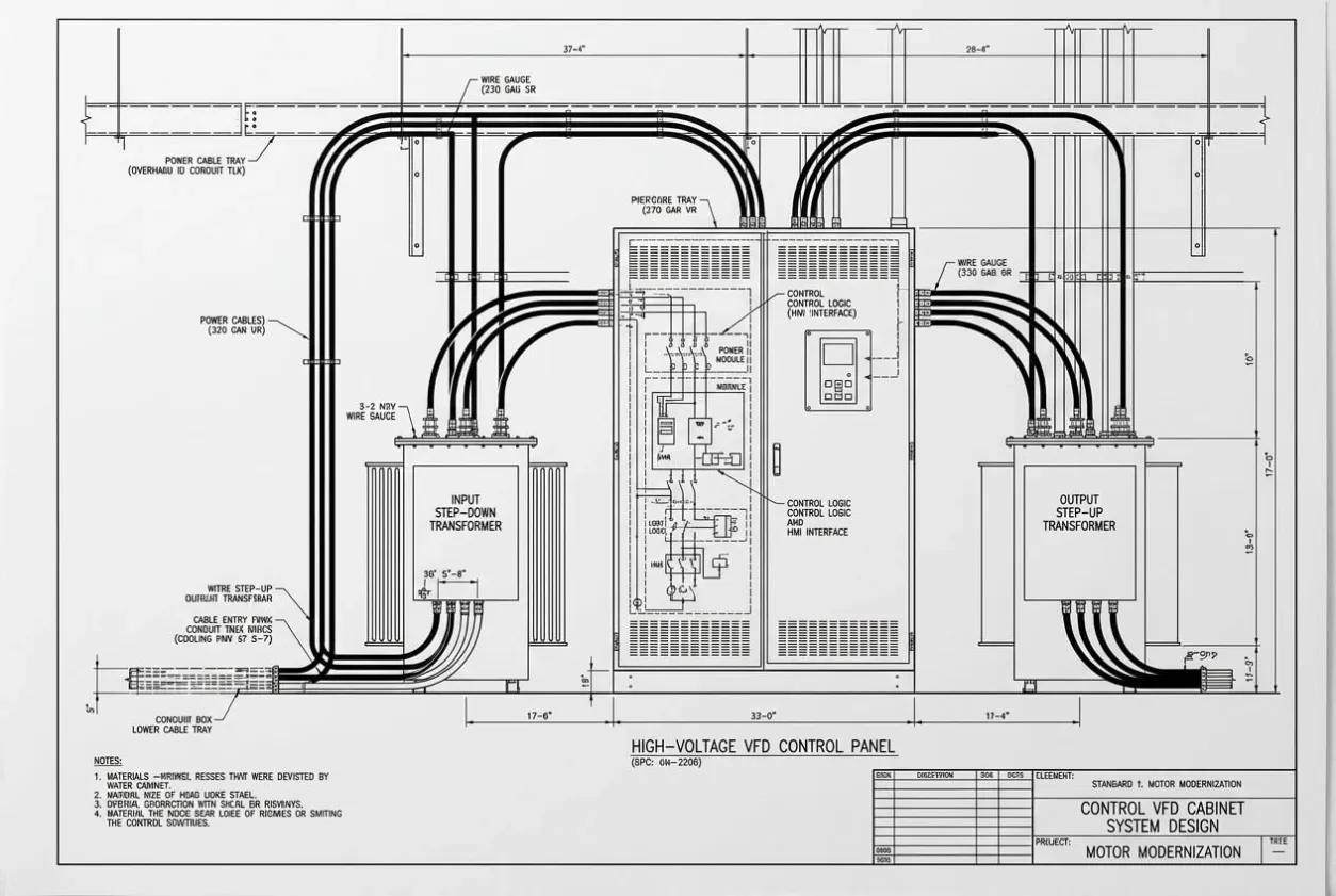
The system architecture used a 690 V VFD platform. The incoming 6.6 kV supply was stepped down to the VFD input voltage. After the VFD controlled the fan speed, the output was stepped up again to feed the existing 6.6 kV motor.
This architecture can be useful, but it is not a shortcut. The transformers are part of the drive system, not accessories added around it. Their voltage ratio, phase relationship, grounding, protection behavior, and thermal condition must be reviewed carefully.
Review Item | Engineering Question | Risk if Ignored |
|---|---|---|
Existing drive condition | Is the old platform becoming a maintenance risk? | Retrofit delayed until failure |
Motor data | Do the 560 kW and 6.6 kV motor details match the new architecture? | Wrong parameter setup or poor motor behavior |
Step-down transformer | Is the VFD input voltage correctly supported? | Drive input fault or abnormal energization |
Step-up transformer | Is the motor voltage correctly restored after the VFD? | Motor heating, torque issue, or trip |
VFD modularity | Can the maintenance team replace power sections quickly? | Longer downtime after a drive fault |
ID fan behavior | Are ramp and speed settings suitable for boiler draft control? | Unstable draft or process disturbance |
PLC interface | Are the permissive, run feedback, trips, and commands correct? | Commissioning delay |
Protection logic | Are VFD, transformer, and motor protections coordinated? | Nuisance trips or unsafe gaps |
Load trial | Can the system run continuously under process conditions? | False confidence after no-load testing |
When Should You Consider This Architecture?
This approach may be suitable when the retrofit is driven by maintainability as much as by motor control.
It may be worth reviewing if:
✓ The existing 6.6 kV motor is still healthy.
✓ The old MV drive platform is becoming obsolete or difficult to support.
✓ Spare-part lead times are increasing.
✓ The maintenance team prefers modular drive platforms.
✓ Downtime recovery is a priority for the plant.
✓ The application is a fan or pump where the transformer-based architecture can be properly engineered.
✓ The site can support the required transformer integration and commissioning checks.
This is not a universal replacement for an MV VFD[^1]. In some projects, a medium-voltage drive remains the best answer. But for selected retrofit cases, the LV VFD with transformer[^2] configuration can reduce long-term maintenance risk if the engineering review is done properly. Before selecting this approach, engineers should compare the advantages and limitations of medium-voltage versus low-voltage VFD solutions[^3] based on the application's electrical, mechanical, and operational requirements.
Critical Engineering Decision
The turning point came during the architecture review.
Everyone expected the medium-voltage option to be the natural answer. It matched the motor voltage directly, looked familiar on the single-line diagram, and would have been easy to defend in a meeting.
But the plant’s real pain was not voltage matching. The real pain was supportability.
Once we looked at the aging drive platform, spare strategy, maintenance capability, and expected recovery time after a fault, the discussion changed. The team stopped asking which option looked more conventional and started asking which option would make life easier for the plant after commissioning.
That was the important shift.
We selected the 690 V modular LV VFD with step-down and step-up transformers because it gave the customer a clearer maintenance path. The trade-off was that the transformer integration had to be engineered carefully. This was not a decision to reduce engineering work. It was a decision to move risk from future downtime into controlled verification during the project.
That is the kind of trade-off I like when it is done honestly.
Question | MV VFD | LV VFD + Transformer |
|---|---|---|
Initial Investment | Often higher for a dedicated medium-voltage drive package, especially when the project scope includes specialized MV equipment and support. | Often lower or more flexible in selected retrofit cases, but transformer cost and integration work must be included. |
Spare Strategy | Spare parts may be more specialized, with longer procurement cycles depending on the platform and region. | Modular LV power sections are often easier to source and replace, supporting a clearer maintenance plan. |
Maintenance | Usually requires technicians familiar with MV drive systems and more specialized service procedures. | More familiar to many plant maintenance teams, especially when the LV platform uses standard modular components. |
Commissioning Complexity | Direct voltage matching can simplify the power architecture, but MV drive commissioning still requires specialist checks. | Transformer integration adds engineering work, including ratio, phase relationship, grounding, protection, and load testing. |
Downtime Recovery | Recovery can be slower if specialized MV components or external service support are required. | Recovery can be faster when spare modules are available and the maintenance team understands the LV platform. |
Best Fit | Suitable when direct MV architecture, site standards, or process requirements justify a dedicated MV drive. | Suitable when the existing MV motor is healthy and long-term maintainability is a major buyer concern. |
We accepted more checks before handover so the customer would face fewer unknowns later. Transformer matching, VFD parameters, protection coordination, PLC I/O, interlocks, no-load testing, and load trial all became part of proving the decision.
The architecture was not accepted because it looked clever. It was accepted because it could reduce operational risk for the buyer.
Solution Delivered
The delivered solution was a 560 kW VFD retrofit for a 6.6 kV ID fan motor using a 690 V low-voltage VFD platform with step-down and step-up transformers.
The plant kept the existing 6.6 kV motor. The incoming supply was reduced to suit the VFD input, and the controlled output was stepped up again for the motor. This allowed the customer to modernize the drive system without replacing the motor or defaulting automatically to a conventional MV VFD package.
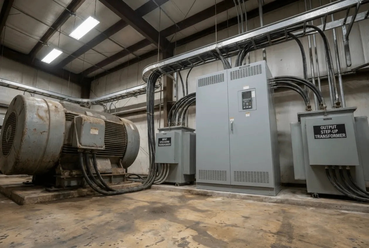
The modular VFD platform was selected because future maintenance mattered. If a power module needs replacement later, the plant has a clearer service route than it had with the aging drive platform. That point may not look dramatic during commissioning, but it matters deeply during a real breakdown.
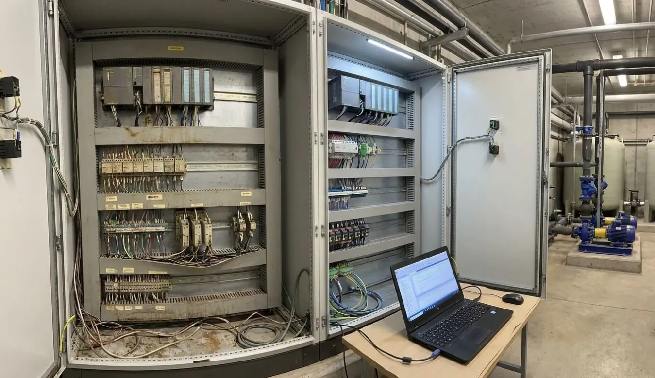
During commissioning, we reviewed the electrical system before energization. Motor data was checked against the VFD parameters. Transformer interfaces were confirmed. Protection and interlock behavior were tested before the fan was placed under process demand.
PLC I/O verification[⁴] also received close attention. In retrofit projects, the drive itself can be healthy while the plant still refuses to run because a permissive trip[⁵], feedback, or remote command is wrong. The new drive had to fit into the existing boiler control[⁶] environment, not just pass its own internal checks.
The no-load test confirmed basic drive response. The load trial then proved the point that mattered most: the fan could operate as part of the boiler system with stable behavior.
Before Shipment Verification
For this retrofit, verification was not only a factory activity. The most important checks happened before energization, during no-load testing, and during the final load trial.
Verification Activity | Why It Mattered |
|---|---|
Existing system review | Confirmed how the old drive was connected and operated |
Motor nameplate check | Verified motor rating, voltage, current, and key parameters |
Transformer integration check | Confirmed the step-down and step-up arrangement |
VFD parameter setup | Matched the drive configuration to fan duty and motor data |
Protection review | Checked VFD, transformer, and motor protection coordination |
PLC I/O verification | Confirmed commands, permissives, trips, and feedback signals |
Interlock testing | Proved unsafe operating conditions would be blocked |
No-load test | Verified basic drive behavior before process loading |
Load trial | Confirmed fan response under real operating condition |
Continuous monitoring | Checked stability beyond initial startup |
Documentation review | Captured settings, test results, and retrofit details |
Maintenance readiness check | Confirmed the service strategy was practical for the plant |
The transformer checks carried real weight. This architecture depends on correct integration, so voltage ratio, phase relationship, grounding, protection, and connection details could not be treated casually.
The PLC I/O test was another high-risk area. Old systems often carry logic that is not fully visible in the first drawing review. A missed permit can delay commissioning even when the VFD is ready. An incorrect feedback signal can make operators doubt a system that is electrically healthy.
The 24-hour load trial became the final evidence. A short no-load run can prove that the drive responds. A continuous load trial proves that the plant can begin to trust the retrofit.
Project Results
The VFD retrofit was successfully commissioned and followed by a 24-hour continuous load trial.
The result was practical and measurable:
- 1 aging high-power drive platform was replaced.
- 1 existing 6.6 kV ID fan motor remained in service.
- 1 new 560 kW VFD system was commissioned.
- 1 transformer-based architecture was verified from a 6.6 kV supply to a 690 V VFD and back to a 6.6 kV motor.
- 2 transformer interfaces were checked and commissioned.
- 4 key areas were verified: power integration, control interface, protection logic, and fan operation.
- 24 hours of continuous load operation were completed after commissioning.
The strongest result was not that the fan started. That was only the first moment of relief.
The stronger result came after the 24-hour load trial. Before the trial, the customer’s concern was whether the transformer-based architecture would really work for a 6.6 kV ID fan. After the trial, the discussion changed. The operations team was no longer focused on whether the retrofit could run. They began to see the system as a maintainable platform for future operation.
That change in confidence was the real outcome.
The boiler team gained a fan control system proven under operating conditions. The maintenance team gained a clearer spare and replacement strategy. The buyer gained something more valuable than a new cabinet: reduced uncertainty around future downtime.
For retrofit projects, that is the result we want. Not only successful commissioning but also less fear when the next maintenance event arrives.
Engineering Notes from Natalie
This project stayed with me because it shows how industrial risk usually grows quietly.
The old drive was not dead. It did not force the plant into an emergency replacement. It kept running, and that made it easy to postpone the decision. But the maintenance people already knew the truth. They knew support was becoming harder. They knew spare parts were less predictable. They knew the next fault might not be solved as quickly as the last one.
That kind of concern does not always appear in a purchase request, but it is often the real reason behind a retrofit.
I also like this case because it challenges a reflex I see often. A 6.6 kV motor does not automatically mean the only answer is an MV VFD. Sometimes it is. Sometimes the better long-term decision is a modular LV VFD with proper transformer integration.
The word “proper” matters. Without careful verification, this architecture would only be a risk. With the right checks, it became a practical way to reduce the customer’s long-term maintenance exposure.
Lessons Learned
Should an aging drive be replaced before it fails?
Yes, if spare availability, service knowledge, or recovery time is becoming uncertain. A drive does not need to be dead before it becomes a business risk.
Does a 6.6 kV motor always require an MV VFD?
No. A medium-voltage VFD is often the direct solution, but selected fan applications can also be reviewed for a 690 V VFD with a step-down and step-up transformer configuration.
What should decide the VFD retrofit architecture?
Voltage rating is only one part of the decision. Maintainability, spare strategy, service capability, downtime risk, and commissioning complexity should also be reviewed.
Where does a transformer-based VFD retrofit usually carry risk?
The main risks are transformer matching, phase relationship, grounding, protection coordination, motor behavior, and VFD output compatibility.
Why is PLC I/O verification so important in retrofit projects?
Because the new drive must work with the existing plant logic. Start commands, permissives, trips, run feedback, and fault signals must all be verified before handover.
Is a no-load test enough for an ID fan retrofit?
No. A no-load test proves basic drive response, but a continuous load trial gives stronger evidence that the fan and boiler system can operate reliably together.
Key Takeaways
✔ A high-power VFD retrofit should be designed around maintainability, not only motor voltage.
✔ A 690 V VFD with transformer configuration can be practical for selected 6.6 kV fan applications.
✔ Transformer integration, PLC I/O, protection logic, and continuous load testing are critical before handover.
Need Similar Support?
Before planning your VFD retrofit, ask yourself whether the real problem is the drive itself or the risk of recovering from the next failure.
If spare-part availability is becoming uncertain, your maintenance team is losing confidence in the existing platform, or downtime recovery is becoming harder to control, the retrofit architecture should be reviewed before a purchase decision is made.
For a high-power fan, pump, or boiler auxiliary system, send us your motor nameplate, existing drive details, single-line diagram, transformer data, and control philosophy.
We can review whether an MV VFD, LV VFD with transformer configuration, or another retrofit approach is more practical for your site conditions, maintenance strategy, and downtime limits.
Engineering Insight
Good retrofit decisions are rarely about today's operation. They are about tomorrow's maintenance.
Related Articles: