Jul 14, 2026Case Studies
Improving Operator Confidence in a DM Water Treatment Plant
PLC-HMI automation for a DM water treatment plant, integrating RO, EDI, dosing control, VFD communication, alarms, and HMI visibility to reduce operator uncertainty and commissioning risk.
When a PLC Does More Than Control—Improving Operator Confidence in a DM Water Treatment Plant
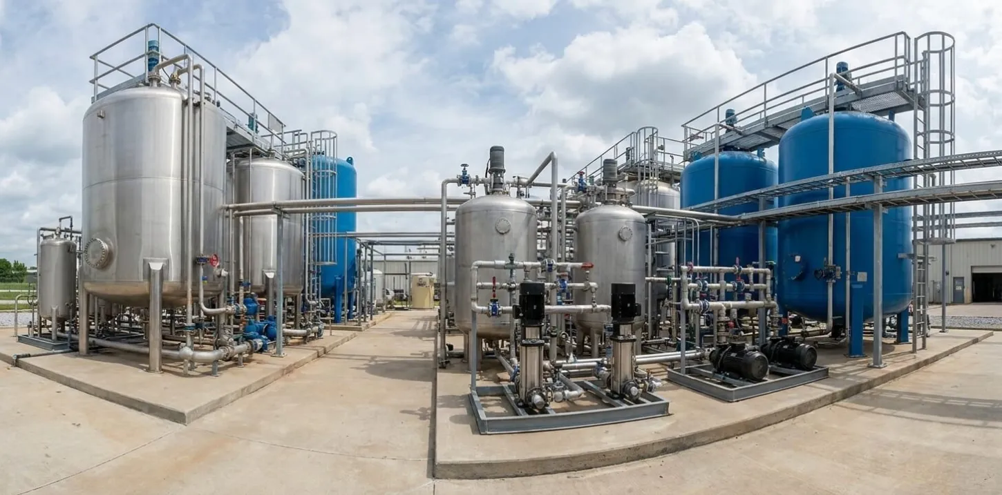
A DM water treatment plant does not usually fail loudly. More often, the problem starts with unclear sequences, unstable dosing, missing feedback, or alarms that do not explain the real cause. This case documents how a PLC-HMI automation system helped reduce operating risk by making the RO, EDI, dosing, VFD, and alarm logic visible and testable before handover.
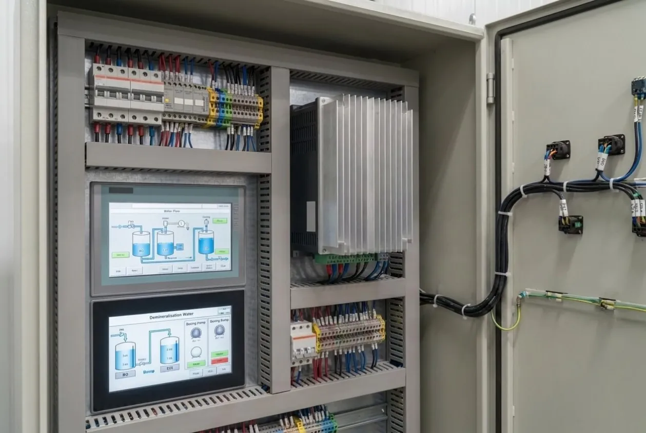
Project Snapshot
Item | Description |
|---|---|
Industry | Water Treatment / Utilities |
Application | Demineralization water treatment plant automation |
Project Type | PLC-HMI control system design, integration, and commissioning |
Location | Confidential |
Products | Siemens S7-1200 PLC, SIMATIC KTP900 HMI, SINAMICS V20 VFD |
Communication | Modbus RTU |
Process Scope | RO system, EDI system, automatic dosing, process monitoring, alarm management |
Services | Control panel engineering, PLC programming, HMI development, VFD integration, field wiring support, commissioning |
Result | Complete PLC-HMI-based automation system commissioned for DM plant operation |
Project Overview
This project involved the design, development, integration, and commissioning of a PLC-HMI-based automation system for a demineralization water treatment plant.
The system included RO[^1] and EDI process automation[^2], automatic dosing control[^3], VFD integration, Modbus RTU communication[^4], alarm management[^5], and real-time plant visualization[^6]. The control system was built around a Siemens S7-1200 PLC[^7], a SIMATIC KTP900 HMI[^8], and SINAMICS V20[^9] VFD integration.
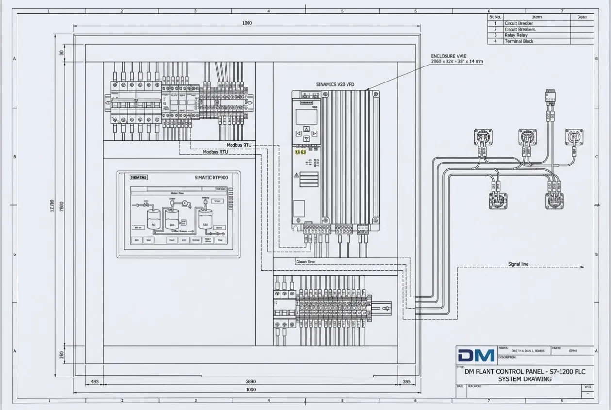
On paper, a DM plant looks straightforward. Pumps start, valves open, dosing runs, the RO system produces water, and the EDI system polishes the output. On site, the story is different. One missing piece can stop a sequence. One unclear alarm can send the operator to the wrong equipment. One unstable dosing signal can affect water quality before anyone understands why.
That was the real concern in this project.
The customer did not need a panel that only turned equipment on and off. They needed a system that could explain the plant condition. If the RO section was not ready, the operator had to know why. If the dosing pump stopped, the HMI had to show whether it was a level issue, interlock, VFD condition, or process alarm.
The project was therefore not only about automation. It was about reducing uncertainty during operation.
Customer Challenge
From the customer’s side, the risk was not a single machine failure. The risk was operating a water treatment process where too much depended on operator memory and manual interpretation.
A DM plant supports production quietly. When it works, few people talk about it. When treated water quality becomes unstable, the effect can move downstream and become more expensive to correct. That is why utility automation needs to be designed with the same discipline as production automation.
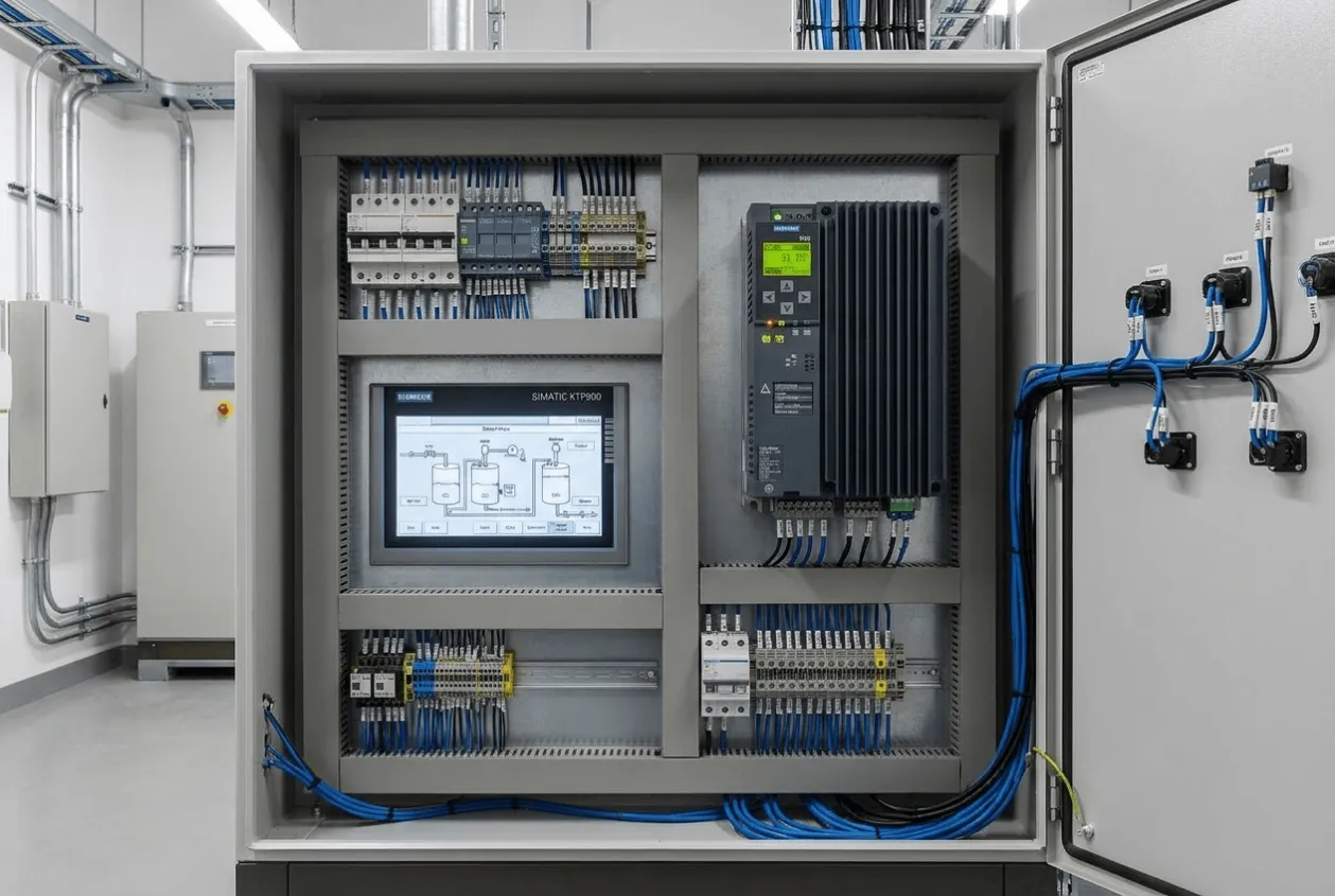
The customer needed better control over RO and EDI sequencing, more consistent dosing behavior, clearer VFD feedback, and an HMI that could help operators understand the process without calling maintenance for every unclear stoppage.
The most painful point was operator confidence.
During commissioning, I always watch how operators look at a new HMI. If they have to keep asking, “Why is this pump not starting?” or “Which alarm came first?” then the screen may look modern, but the automation has not reduced risk.
That was the buyer trigger in this project. The customer needed a control system that helped the team operate the plant with fewer guesses. A PLC can execute logic, but a good automation system must also make that logic understandable.
Engineering Review
The engineering review started from the process sequence, not from the HMI graphics.
This was important. If the sequence logic is weak, the HMI only displays weak logic in a nicer way. For a DM water treatment plant, the control philosophy must first answer how the RO section starts, what conditions allow EDI operation, when dosing is enabled, how VFD faults are handled, and what should happen when a critical alarm appears.
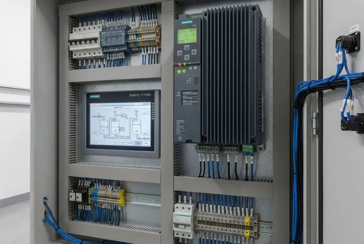
The PLC program had to manage equipment readiness, automatic operation, interlocks, alarms, VFD communication, dosing commands, and operator control. The HMI had to turn that logic into something usable for the people standing in front of the panel.
Review Item | Engineering Question | Risk if Ignored |
|---|---|---|
RO sequence | Are flushing, start permissives, stop logic, and protection conditions clear? | Poor process stability or equipment stress |
EDI automation | Is EDI operation protected by correct upstream conditions? | Water quality risk or equipment protection issue |
Dosing control | Is dosing linked to process need instead of manual habit? | Overdosing, underdosing, or unstable quality |
VFD integration | Are ready, run, fault, and command signals useful to the PLC? | Drive fault confusion during operation |
Modbus RTU | Are communication settings and register mapping verified? | Missing data or unreliable control |
HMI design | Can the operator understand the plant condition quickly? | Slow response during abnormal conditions |
Alarm logic | Does the alarm point to the root cause? | Alarm fatigue and longer troubleshooting |
Control panel | Is wiring traceable and serviceable? | Difficult maintenance after handover |
Commissioning | Are software functions tested against real field signals? | Logic works in simulation but fails onsite |
When Should You Consider This Automation Architecture?
A PLC-HMI-based automation system should be considered when the plant risk is no longer only mechanical or electrical but operational.
This approach may be suitable if:
✓ Operators depend on manual sequencing for RO, EDI, or dosing operation.
✓ Alarm information is available but does not help identify the real cause.
✓ Dosing stability affects downstream process quality.
✓ VFD faults or communication issues take too long to diagnose.
✓ The plant needs real-time visualization for operation and maintenance.
✓ Existing relay logic or manual control makes expansion difficult.
✓ The customer wants better commissioning evidence before handover.
This is the point buyers should notice. Automation is not only about reducing manpower. In a DM plant, automation should reduce the risk of wrong operation, slow diagnosis, and unstable water quality.
Critical Engineering Decision
The turning point came when the project discussion moved away from “Can the PLC run the plant?” and became “Can the operator understand why the plant is not running?”
That changed the design.
At the beginning, it would have been easy to build a normal PLC program with start-stop logic, a few interlocks, some alarm tags, and basic HMI screens. The plant would probably run under normal conditions. But normal conditions are not where operators need help the most.
The real test comes when something blocks the sequence.
If the RO feed pump is not starting, the operator needs to see the actual blocking condition. If the EDI system is unavailable, the HMI should not force the technician to search through several pages before finding the cause. If the dosing pump is stopped, the screen should help distinguish between command, interlock, tank level, VFD fault, and process condition.
This decision changed the project from equipment control to risk reduction.
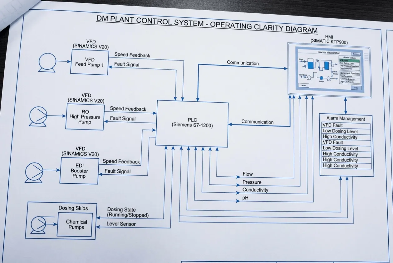
We designed the PLC and HMI around operating clarity. Alarm management, equipment status, VFD feedback, dosing state, and process visualization were connected so the system could explain itself during abnormal operation.
That extra effort matters. A plant that runs only when everything is perfect is not a reliable plant. A reliable plant helps operators recover when something is wrong.
Solution Delivered
The delivered solution was a complete PLC-HMI automation system for the DM water treatment plant.
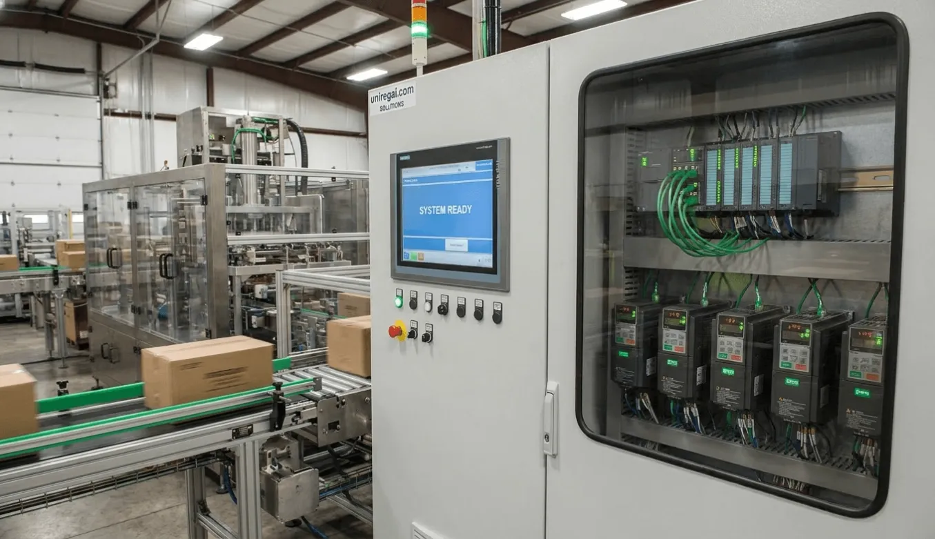
The Siemens S7-1200 PLC handled process control logic, automatic sequences, equipment interlocks, dosing commands, alarm handling, and communication with the VFD. The SIMATIC KTP900 HMI provided operator control, real-time visualization, equipment status, alarm display, and process monitoring.
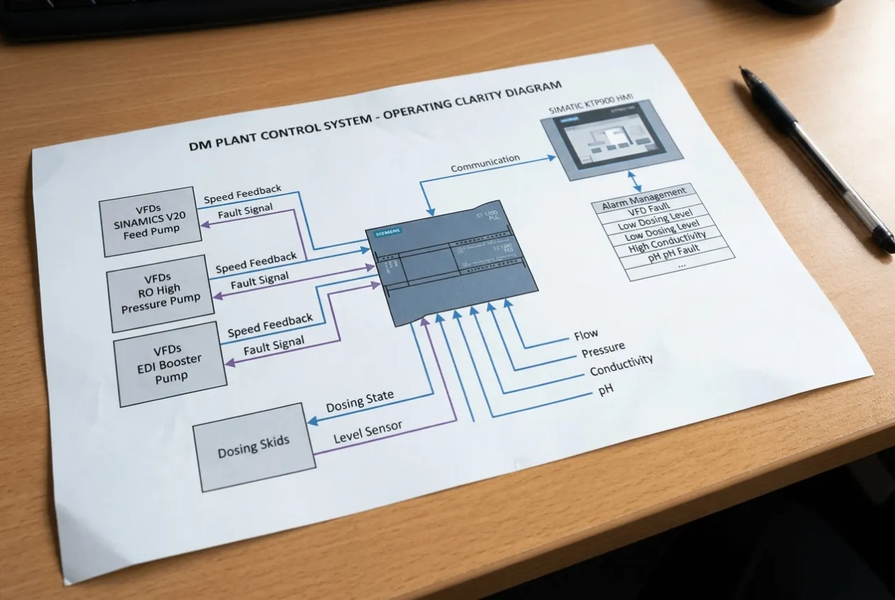
The SINAMICS V20 VFD was integrated through Modbus RTU communication. This gave the PLC better access to drive status than a simple hardwired command arrangement. The system could monitor whether the VFD was ready, running, faulted, or unavailable.
The RO and EDI sections were automated according to process conditions. Dosing control was integrated into the logic so chemical addition followed the intended plant operation rather than depending only on manual adjustment.
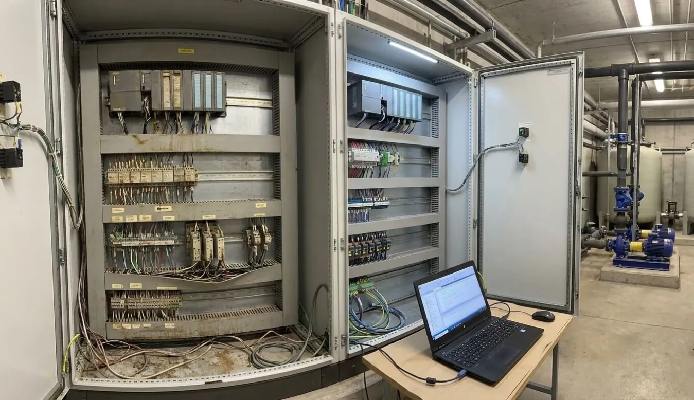
The control panel was engineered for field use. Wiring, terminal layout, labeling, and device arrangement were reviewed so the maintenance team would not inherit a confusing cabinet after commissioning. A clean panel is helpful, but a traceable panel is more valuable.
The final system gave the customer a plant that was easier to operate, easier to monitor, and easier to troubleshoot.
Before Shipment Verification
Before delivery and commissioning, the control system went through verification to reduce site risk.
For a DM plant, verification must connect software, hardware, communication, and process logic. Testing the PLC program alone is not enough. Testing the panel wiring alone is not enough. The system must be checked as one operating package.
Verification Activity | Why It Mattered |
|---|---|
Component verification | Confirmed PLC, HMI, VFD, power supply, terminals, and control devices matched the design |
Wiring inspection | Checked internal wiring, ferrules, terminal numbers, and cable routing |
Continuity testing | Verified control circuits before energization |
PLC program review | Checked sequence logic, interlocks, alarms, and control modes |
HMI screen test | Confirmed operator pages showed useful plant information |
Modbus RTU test | Verified communication between PLC and VFD |
VFD function test | Confirmed control and status feedback from the SINAMICS V20 |
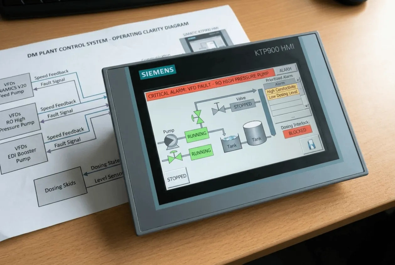
Alarm simulation | Checked whether alarms appeared clearly on the HMI |
Dosing control test | Verified automatic dosing command behavior |
RO and EDI sequence test | Confirmed process stages followed intended logic |
Field I/O verification | Matched real field signals with PLC inputs and outputs |
Documentation review | Confirmed drawings and I/O references matched the final system |
The Modbus RTU test was one of the checks we treated carefully. Communication faults can waste a lot of commissioning time because they often look simple from outside. The cable may be correct, the device may be powered, and the VFD may be healthy, but one wrong address, baud rate, parity setting, or register map can stop useful data from reaching the PLC.
The HMI test was equally important. I do not like screens that look good but do not help the operator. We checked whether common questions could be answered quickly: what is running, what is stopped, what is blocked, and what alarm should be checked first.
The system was considered ready only after logic, communication, indication, and field response were verified together.
Project Results
The PLC-HMI automation system was successfully designed, integrated, and commissioned for the DM water treatment plant.
The result was practical and measurable, but the real value was seen in how the plant became easier to understand during operation.
The project delivered one Siemens S7-1200 PLC program, one SIMATIC KTP900 HMI application, one SINAMICS V20 VFD integration, one verified Modbus RTU communication layer, automated RO and EDI sequences, automatic dosing control, and alarm management inside one operating environment.
Those numbers mattered, but the impact mattered more.
Operators no longer needed to trace multiple screens to understand why an RO sequence was blocked. When a device was not running, the HMI helped point toward the reason instead of only showing a stopped status. VFD information became part of the control system, so the team could see whether the issue was a command problem, a drive condition, or an interlock. Dosing control became more consistent because it was tied to the process logic instead of depending only on manual adjustment.
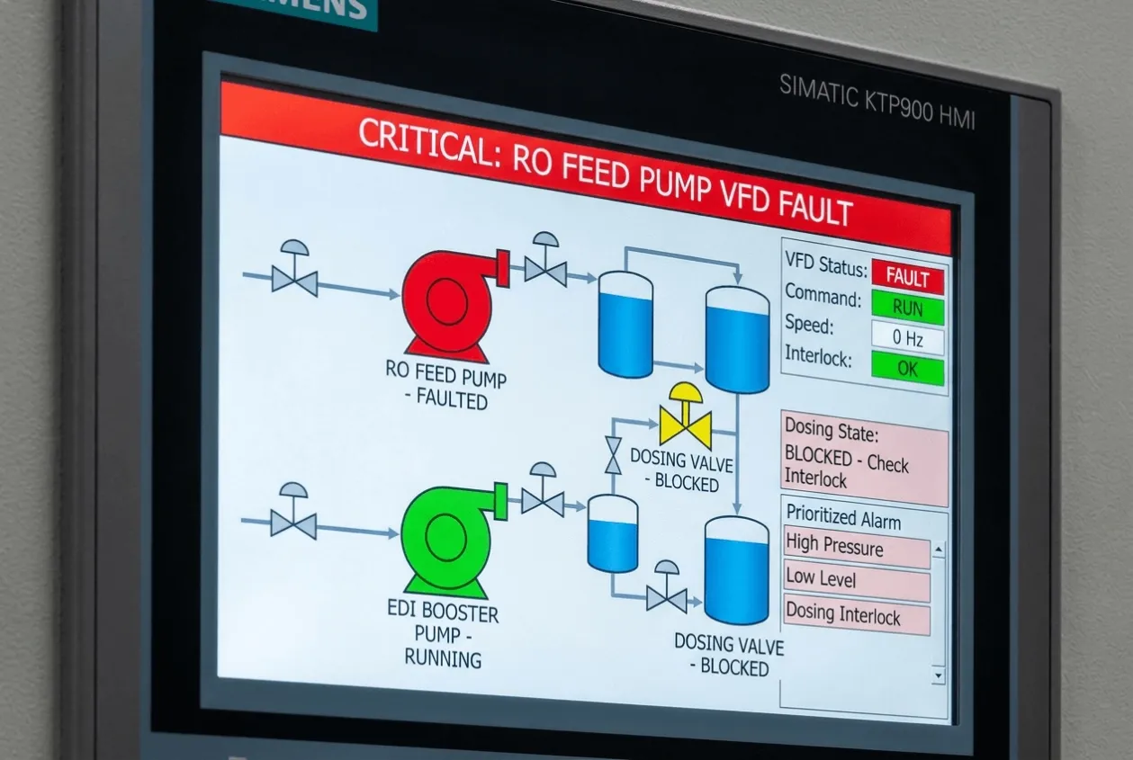
After commissioning, the customer gained better process visibility. The maintenance team gained clearer fault information. The operator gained a system that could show why equipment was running, stopped, blocked, or in alarm.
For the buyer, the value was reduced operating risk. The automation did not only make the plant smarter. It made the plant easier to understand when something was wrong.
That is the moment a control system starts to earn trust.
Engineering Notes from Natalie
DM plant automation looks simple until you stand in front of the panel during commissioning.
The drawing shows a clean process. The real plant asks questions. Why is the pump not starting? Why did the dosing stop? Why is the VFD ready but not running? Why is the EDI section waiting?
These questions decide whether the automation is useful.
I have seen systems where the PLC logic was technically correct, but the operator still had to guess what was happening. That is not good automation. A control system should reduce the pressure on the person operating it. It should not hide the logic behind nice graphics.
This project reminded me that clarity is an engineering decision. It has to be designed into the PLC logic, HMI structure, alarm text, and commissioning tests.
When a plant can explain its own condition clearly, operators become calmer. That is not just a nice feeling. It reduces mistakes.
Good automation does not remove operators. It removes uncertainty.
Lessons Learned
Why should RO and EDI automation be designed as a sequence?
Because water quality depends on process order, permissives, flushing, interlocks, and protection conditions. Individual device control is not enough for stable DM plant operation.
What is the risk of weak alarm management in a DM plant?
Operators may see an alarm but still miss the root cause. Alarm logic should help identify what happened first and what action is required.
Why does VFD communication matter?
A VFD should provide useful operating feedback. Ready status, run feedback, fault condition, and communication health help operators and technicians diagnose issues faster.
Is a good HMI only about graphics?
No. A good HMI explains the plant condition clearly. The operator should understand why equipment is running, stopped, blocked, or faulted.
Why should dosing control be automated?
Manual dosing can create inconsistency. Automatic dosing control helps improve process stability and reduces dependency on operator adjustment.
What should be verified before commissioning?
PLC logic, HMI screens, VFD communication, field I/O, alarms, interlocks, dosing behavior, and RO/EDI sequence should be tested together before handover.
Key Takeaways
✔ DM plant automation should reduce operator uncertainty, not only replace manual control.
✔ RO, EDI, dosing, VFD communication, and alarm logic must be tested as one system.
✔ A clear HMI helps operators understand the plant faster and reduces troubleshooting risk.
Engineering Insight
For a DM water treatment plant, the most important automation question is not “Which PLC should we use?” It is “Can the system explain the process clearly when operation becomes abnormal?”
Many plants already have pumps, valves, dosing units, RO skids, and EDI equipment installed. The real weakness often appears at the control layer. Operators can see that something has stopped, but they cannot quickly see why. Maintenance teams can open the panel, but they still need time to trace signals, check interlocks, and confirm whether the fault came from the process, the VFD, the dosing system, or the sequence logic.
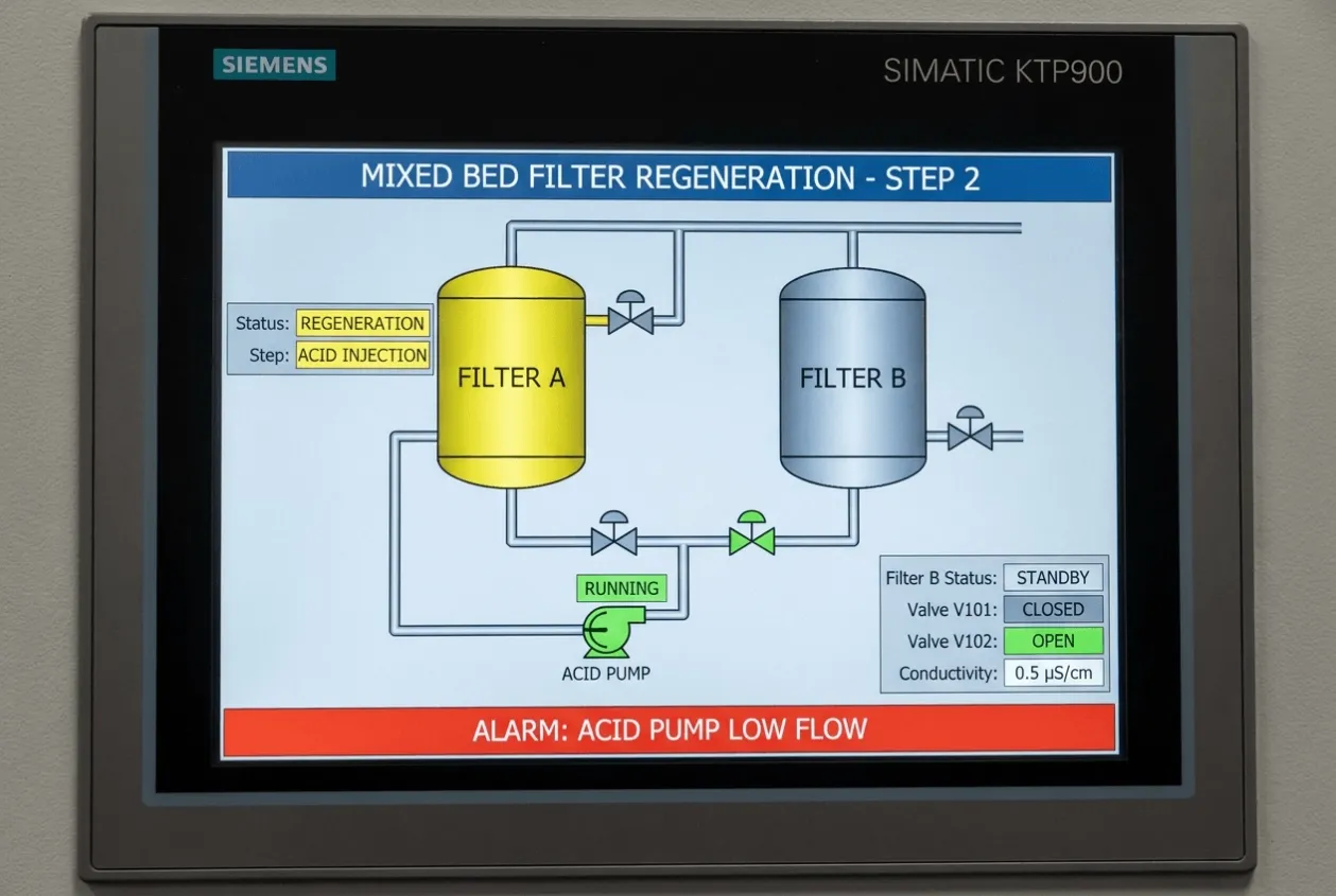
That is where PLC-HMI engineering reduces risk.
A good DM plant automation system should make the plant easier to diagnose, not only easier to start. The HMI should show blocked conditions clearly. The PLC should manage permissives in a way that protects the process. Alarm text should guide the operator toward the first cause, not only display the final symptom.
For buyers planning RO, EDI, dosing, or utility automation projects, do not evaluate the control system only by hardware brand. Evaluate whether it will reduce troubleshooting time, operator confusion, and water quality risk after commissioning.
Need Similar Support?
Before automating a DM water treatment plant, ask whether your current system helps operators understand problems or only shows that a problem exists.
Typical situations include the following:
• RO systems with frequent operator intervention
• EDI systems with unclear sequence logic
• Dosing systems requiring stable automatic control
• Plants with recurring alarm confusion
• VFD faults that take too long to diagnose
• Existing relay-based control panels ready for PLC migration
If manual sequencing, unclear alarms, unstable dosing, limited process visibility, or slow fault diagnosis is creating risk, the control architecture should be reviewed before panel fabrication.
For a DM plant, RO/EDI system, dosing skid, pump control panel, or utility automation project, send us your P&ID, I/O list, control philosophy, equipment list, and communication requirements.
We can review the PLC-HMI architecture, alarm strategy, VFD integration, dosing logic, and commissioning checks needed to reduce operation and maintenance risk before the system reaches site.
Related Articles: