
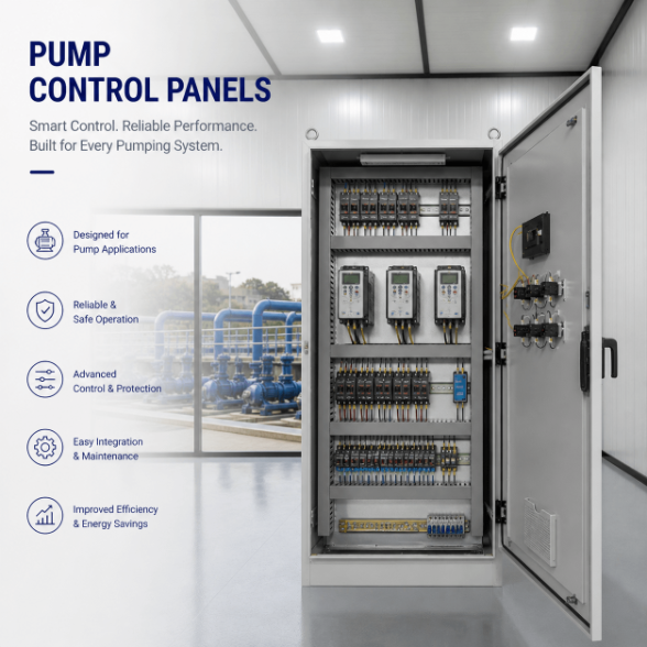
Pump Control Panels
Pump Control Panel Supplier
Pump control panels for single-pump, duplex, booster and transfer duty — with enclosures, VFDs and protection sized to your site. Source from Foshan suppliers.
Specifications
- Application
- Custom Industrial Automation
- Control Method
- PLC / Relay Based
- Voltage
- 220V / 380V / 480V Available
- Protection Rating
- IP54 / IP65 Optional
- CCommunication Protocol
- Modbus / Profinet / Ethernet/IP
- Testing
- FAT Before Shipment
- Customization
- Available
PLC Control Panel for Defined Logic, I/O and System Integration
UniRegal supplies custom PLC Control Panels for industrial machinery, production lines, water treatment, pump systems, HVAC equipment, process automation and OEM projects.
A PLC Control Panel should not be specified only by PLC brand or I/O quantity. The real project scope depends on what the system must do, which field devices it must control, how failures should be handled, what information operators need and who is responsible for programming, testing and commissioning.
The most successful projects define these boundaries before the panel is built.
Send us your I/O list and control sequence for technical review.
Quick Answer
A PLC Control Panel is an industrial electrical panel that uses a programmable logic controller to receive field inputs, execute approved control logic and send commands to motors, valves, actuators, relays and other equipment.
It may also include an HMI, remote I/O, communication modules, control power supplies, safety devices, terminals and interfaces to VFDs, MCCs, SCADA, BMS or other control systems.
The PLC hardware controls the system, but the I/O definition, program logic and interface responsibilities determine whether the panel will work after installation.
The Hard Part Is Not Choosing a PLC
Most PLC brands can receive inputs, execute logic and control outputs. Project problems usually begin elsewhere.
Common causes of commissioning delay include:
- An incomplete I/O list
- Control logic that was never formally approved
- Different interpretations of Manual and Auto mode
- Missing permissives or shutdown conditions
- HMI alarms that do not explain the actual fault
- VFD or instrument data that was assumed but never mapped
- Unclear responsibility for PLC or HMI programming
- Communication protocols defined without a tag or register list
- Safety functions mixed into standard control logic
- No agreement about source-code ownership
- FAT completed without defined acceptance criteria
- Site changes that were never added to the final program backup
A PLC Panel can be wired correctly and still fail to operate the process correctly. Electrical completion and functional completion are different acceptance points.
Buyer Decision Information: Define the Supply Scope First
Before comparing PLC Control Panel quotations, determine which engineering model the project requires.
Supply Model | Customer Provides | Supplier Scope | Best Fit |
|---|---|---|---|
Build-to-Print Panel | Approved drawings, BOM, I/O wiring and hardware list | Procurement, assembly, wiring and agreed inspection | OEMs and system integrators with completed designs |
Panel Design and Build | I/O list, power requirements, field-device data and project standards | Electrical design, drawings, hardware selection, assembly and testing | Projects with defined controls but incomplete panel drawings |
PLC/HMI Programming | Approved functional description, I/O list, alarm list and screen requirements | PLC logic, HMI development and agreed software FAT | New machines and process automation |
Integrated Control Package | Process information, operating philosophy and interface requirements | Panel design, PLC/HMI software, communications and agreed testing | Projects needing coordinated electrical and automation delivery |
Retrofit or Migration | Existing panel information, software backup and operational description | Legacy review, migration design, panel replacement and cutover planning | Existing equipment with obsolete or unsupported controls |
The quotation should state clearly whether it includes electrical design, panel manufacturing, PLC programming, HMI development, SCADA integration, site commissioning, operator training and final source files.
The phrase “complete PLC Panel” does not define these responsibilities by itself.
Documents That Should Exist Before Programming
PLC programming should be based on approved functional information rather than verbal assumptions.
Control Narrative
The control narrative, also called a sequence of operations or functional description, explains how the equipment should start, run, stop and respond to normal and abnormal conditions.
It should define:
- Startup conditions
- Operating sequence
- Manual and automatic modes
- Permissives
- Interlocks
- Trip conditions
- Alarm conditions
- Restart behaviour
- Power-failure response
- Communication-loss response
- Operator actions
- Maintenance or bypass modes
I/O List
The I/O list identifies every signal entering or leaving the PLC system. A total I/O count is not enough because different signal types require different modules, wiring and engineering.
Cause-and-Effect Matrix
For process and utility systems, a cause-and-effect matrix can show which alarm, trip, shutdown or equipment response should occur when a defined condition becomes true.
Alarm List
The alarm list should define the tag, message, trigger condition, delay, priority, acknowledgement requirement and reset behaviour.
HMI Screen List
The screen list defines the operating pages, overview displays, equipment pop-ups, trends, alarms, settings, recipes and maintenance information required by the user.
Communication List
The communication list defines which devices exchange data, which system initiates communication and which tags or registers must be transferred.
Without these documents, the quotation may include the correct PLC hardware but still leave the main engineering work undefined.
I/O Design: Point Count Is Only the Beginning
Each I/O point should define more than whether it is an input or output.
I/O Information | Example |
|---|---|
Tag Number | LT-101, P-201_RUN or XV-301_OPEN |
Signal Type | DI, DO, AI, AO, RTD, thermocouple or pulse |
Electrical Signal | 24VDC, dry contact, 4–20mA, 0–10V or project-specific |
Field Device | Sensor, switch, valve, relay, VFD or instrument |
Normal State | Normally open, normally closed or defined process state |
Fail State | Energize, de-energize, hold, stop or alarm |
Isolation Requirement | Standard, individually isolated or barrier interface |
Location | Local panel, remote I/O or field junction box |
Control Function | Indication, permissive, interlock, command or shutdown |
HMI Requirement | Display, alarm, trend, setpoint or operator command |
The review should also distinguish among:
- Standard digital I/O
- Analog instrumentation
- RTD and thermocouple inputs
- High-speed counters or pulse inputs
- Encoder or motion signals
- Safety I/O
- Remote I/O
- Spare installed I/O
- Spare rack or network capacity
A quotation that lists “100 I/O points” without identifying the signal mix is not sufficiently defined.
Centralized PLC or Remote I/O?
Centralized I/O
Centralized I/O may be suitable when field devices are close to the PLC Panel and the cable routes are manageable.
It simplifies the controller architecture but may require more field cabling and larger terminal sections.
Remote I/O
Remote I/O may reduce long field-cable runs by locating I/O stations closer to equipment or process areas.
The design must still define:
- Network topology
- Communication medium
- Power supply
- Enclosure environment
- Addressing
- Network-loss behaviour
- Local isolation
- Diagnostic access
- Spare capacity
- Ownership of field wiring
Remote I/O reduces some wiring, but it adds network and distributed-power dependencies that must be included in the FAT and commissioning plan.
Redundant PLC Architecture
Redundant controllers, power supplies, communication paths or I/O may be considered for processes where controller failure has a defined operational consequence.
Redundancy should not be added only as a marketing feature. The project should identify the required availability, acceptable switchover behaviour, maintenance method and which elements must remain redundant.
How to Select the PLC Platform
The best PLC is not automatically the most expensive or powerful model.
The platform should be selected according to:
- Required I/O quantity and signal types
- Processing and memory requirements
- Scan-time or motion requirements
- Local and remote I/O architecture
- Communication protocols
- Redundancy requirements
- Safety functions
- HMI and SCADA compatibility
- Installed equipment base
- Local engineering support
- Spare-parts availability
- Software licensing
- Product lifecycle
- Customer programming standards
- Maintenance-team familiarity
Available platforms may include Siemens, Allen-Bradley, Schneider Electric, Omron, Mitsubishi, ABB, Delta, LS and other project-specified brands.
The final platform and exact part numbers must be confirmed before quotation because different PLC families from the same brand can have significantly different capabilities, software requirements and lifecycle status.
PLC and HMI: Define What the Operator Must Understand
An HMI should not be selected only by screen size.
A useful HMI helps the operator understand:
- What is running
- What is stopped
- Why equipment cannot start
- Which permissive is missing
- What caused a trip
- Which action is required
- Whether the system is in Manual or Auto
- Which setpoints can be changed
- Who changed a parameter
- Whether communication has failed
The HMI scope should define:
HMI Requirement | Buyer Decision |
|---|---|
Screen List | Which overview, equipment and maintenance pages are required? |
Alarm Philosophy | How are alarms prioritized, delayed, acknowledged and reset? |
User Access | Which functions require operator, maintenance or administrator access? |
Manual Control | Which devices may be operated individually? |
Setpoints | Which values can be changed, and what are the allowed limits? |
Trends | Which process values need historical or real-time display? |
Recipes | Are multiple product or process settings required? |
Languages | Is one language or multilingual operation required? |
Data Logging | Is local storage or transfer to SCADA required? |
Time Synchronization | Which device provides the system time? |
An HMI that shows only green and red equipment symbols may satisfy a screen count while providing very little troubleshooting value.
PLC, VFD and Motor Control Interfaces
A PLC Control Panel may send commands to VFDs, motor starters or MCC feeders through hardwired signals or industrial communication.
The interface should define:
- Start and stop command
- Available or ready status
- Run feedback
- Fault or trip status
- Local or remote status
- Speed reference
- Actual speed or frequency
- Motor current
- Reset command
- Interlock conditions
- Communication-loss response
The PLC controls the operating logic, while the Motor Control Panel or MCC provides the motor power switching and protection.
If VFDs are installed inside the PLC Panel, the design must also review drive heat, ventilation, EMC, cable routing and separation between power and low-level control signals.
Communication Must Be Defined Beyond the Protocol Name
Writing “Modbus,” “PROFINET” or “EtherNet/IP” in a specification does not complete the communication design.
For every connected device or system, confirm:
- Communication protocol
- Physical connection
- Device role
- IP address or node address
- Baud rate where applicable
- Tag or register mapping
- Data format and scaling
- Update rate
- Command permissions
- Diagnostic information
- Timeout
- Retry behaviour
- Action after communication loss
- Time synchronization
- Network-switch requirements
- Responsibility for configuration
A PLC may communicate successfully with a device while the project still fails because the wrong tags, units, byte order or control authority were assumed.
Remote Access and Industrial Network Security
Remote support can reduce travel and troubleshooting time, but the PLC should not be exposed directly to the public internet.
Where remote access is required, the project should define:
- Approved VPN, gateway or secure remote-access method
- Firewall and network segmentation
- User accounts and access levels
- Multi-factor authentication where supported
- Session approval and logging
- Time-limited access
- Removal of default passwords
- Backup before remote modification
- Management of software and firmware versions
- Ownership of the remote-access account
- Procedure for disabling access
Unused network services should be disabled where practical, and remote-access credentials should not be shared as a general project password.
Cybersecurity scope must be agreed with the customer’s OT and IT policies before commissioning.
Software Ownership and Version Control
The PLC and HMI programs are part of the delivered automation system, but the required handover scope is often left unclear until the end of the project.
Before ordering, confirm whether the delivery includes:
- Native editable PLC source project
- Native editable HMI project
- Compiled runtime files
- PLC hardware configuration
- Communication configuration
- VFD and device parameter backups
- Required software licenses
- Library or add-on instruction dependencies
- Device-description files
- User accounts and passwords
- Program comments and tag descriptions
- Version history
- FAT-approved backup
- Final as-commissioned backup
- Password-protection policy
- Permission for future modification
The quotation should distinguish between a working program and a complete editable engineering package.
After site changes, the final backup should be updated and clearly identified. Otherwise, the customer may later restore an older program and unknowingly remove commissioning modifications.
Build-to-Print, Custom Design and Programming Scope
Build-to-Print PLC Panel
The customer provides approved electrical drawings, BOM, I/O wiring, PLC hardware configuration and labeling requirements. UniRegal manufactures and wires the panel according to the confirmed documents.
PLC or HMI programming is not automatically included unless it is listed in the supply scope.
Custom PLC Panel Design
The customer provides the application, I/O list, control narrative, field devices, electrical supply, environment and preferred platform. Electrical schematics, hardware selection and panel layout are then developed for approval.
PLC and HMI Programming
Programming requires an approved functional specification, I/O database, alarm philosophy, screen list and interface definition.
Programming hours and FAT scope cannot be estimated accurately from the PLC model and I/O quantity alone.
Retrofit and Migration
Retrofit projects require an additional review of the existing hardware, software, field wiring and process operation before a replacement architecture can be defined.
PLC Retrofit and Migration Planning
An old PLC Control Panel may still operate while creating increasing maintenance risk because of obsolete CPUs, unavailable I/O modules, unsupported HMI software or missing backups.
A retrofit should begin with an inventory of:
- Existing PLC, I/O and HMI models
- Current program and software version
- Password or access restrictions
- Existing communication networks
- Field-voltage and signal types
- Wiring and terminal condition
- Active and unused I/O
- Existing alarms and interlocks
- Operator procedures
- VFD and instrument interfaces
- Available shutdown window
- Required rollback plan
The migration plan should then define:
- Hardware replacement
- I/O conversion
- Tag mapping
- Program conversion or rewrite
- HMI migration
- Network changes
- Field-wiring modifications
- Simulation and FAT
- Cutover sequence
- Site testing
- Backup and rollback
- Operator and maintenance training
A successful PLC migration is not measured only by whether the new CPU enters RUN mode. The existing process must continue to operate as expected after the control platform changes.
What Buyers Should Compare Between PLC Panel Quotations
Comparison Point | Why It Matters |
|---|---|
Hardware-Only or Programmed Scope | Determines whether PLC and HMI engineering is included |
Approved I/O Basis | Confirms the signal quantity and type being priced |
Spare I/O | Must distinguish installed modules from rack capacity |
Control Narrative | Defines the logic to be implemented |
HMI Screen and Alarm Scope | Determines operator functionality |
Communication Mapping | Defines usable integration rather than protocol compatibility |
Safety Scope | Distinguishes standard PLC logic from safety functions |
Source-Code Delivery | Determines future access and modification rights |
Software Licenses | May create additional customer cost |
FAT Method | Defines whether testing covers wiring only or functional logic |
Site Commissioning | Determines who verifies the real process |
Documentation | Affects maintenance and future modification |
Remote-Access Security | Defines how external support is controlled |
Change Management | Determines which program version becomes the final record |
Two suppliers can quote the same PLC and I/O modules while offering completely different engineering, software and acceptance scopes.
Technical Configuration Options
Parameter | Available Configuration |
|---|---|
Product | PLC Control Panel / PLC Automation Panel |
Application | Machinery / Process / Utility / Building Automation |
PLC Architecture | Compact / Modular / Remote I/O / Project-Specific Redundancy |
I/O | Digital / Analog / RTD / Thermocouple / Pulse / Project-Specific |
HMI | Local Touchscreen / Remote HMI / SCADA Interface |
Motor Interface | Hardwired Starter / VFD / MCC Communication |
Communication | Modbus RTU/TCP / PROFINET / EtherNet/IP / PROFIBUS / BACnet |
Control Modes | Local / Remote / Manual / Automatic |
PLC Brands | Siemens / Allen-Bradley / Schneider / Omron / Mitsubishi / ABB / Delta / LS |
Control Power | 24VDC or Project-Specified |
Enclosure | Wall-Mounted / Floor-Standing / Indoor / Outdoor |
Material | Powder-Coated Steel / Stainless Steel |
Protection Rating | Selected According to the Environment |
Documentation | Schematics / I/O List / Terminal Plan / Network Diagram / Test Records |
Software | Customer-Supplied / Developed to Approved Functional Scope |
Standards | Applicable Project, IEC or UL Requirements Subject to Confirmation |
Final hardware, software, certification and test scopes are confirmed from the approved project information.
Electrical and Panel Design Considerations
The PLC may be the main controller, but the surrounding electrical design affects signal stability and maintenance.
The panel review should consider:
- Incoming and control-power protection
- Power-supply loading and redundancy where required
- Separation of power, control and communication wiring
- Analog signal routing
- Shield termination
- Grounding and bonding
- Interposing relays
- Individually fused circuits where specified
- Terminal grouping by voltage and function
- Field-disconnect requirements
- Heat from power supplies, VFDs and other devices
- Enclosure environment
- Spare terminals and I/O
- Service access
- Clear wire, device and terminal labels
Analog and communication problems discovered during commissioning are often caused by wiring, grounding or interface assumptions rather than PLC program errors.
Factory Acceptance Testing
PLC Control Panel FAT should be based on an approved test procedure and functional design basis.
Typical FAT items may include:
- Hardware and part-number verification
- Panel layout and wiring inspection
- Grounding and protective bonding
- Control-power verification
- PLC hardware configuration
- I/O module detection
- Digital I/O simulation
- Analog signal simulation and scaling
- PLC logic sequence testing
- Permissive and interlock testing
- Alarm generation, acknowledgement and reset
- Manual and automatic mode testing
- HMI navigation and operator-control checks
- Setpoint and access-level checks
- VFD or intelligent-device communication
- SCADA or external-system interface testing
- Communication-loss simulation
- Power-cycle and restart-behaviour testing
- Backup and restore verification
- Software-version recording
- Drawing, tag and program consistency review
Test cases should record the expected result, actual result, pass or fail status, comments and responsible approval.
What FAT Does Not Automatically Prove
When field devices and process equipment are unavailable, FAT relies on simulated inputs and outputs.
It does not automatically prove:
- Actual sensor calibration
- Final motor rotation
- Valve travel or actuator behaviour
- Process response under real load
- PID tuning
- Field-network performance
- Site cable integrity
- Complete safety validation
- Operator readiness
- Performance under every abnormal process condition
These items require Site Acceptance Testing, commissioning or a separately agreed validation scope.
Engineering Documentation
Depending on the project scope, available documentation may include:
- General arrangement drawing
- Electrical schematic
- Power-distribution diagram
- PLC hardware configuration
- I/O list
- I/O wiring diagram
- Terminal plan
- Cable schedule
- Bill of materials
- Control narrative
- Cause-and-effect matrix
- Alarm list
- HMI screen list
- Network architecture
- Communication mapping
- Device address list
- Software-version register
- FAT procedure and report
- PLC and HMI backups
- VFD and instrument parameter backups
- As-built documentation
- Packing list
Required documents, file formats, software versions and approval stages should be agreed before production.
Information Required for a Quotation
Required Information | Example |
|---|---|
Application | Machine, process, water treatment, HVAC or pump system |
Control Narrative | Startup, operation, shutdown, alarms and failure response |
I/O List | Signal tags, types, ranges and field devices |
PLC Platform | Preferred brand, CPU family and programming software |
HMI Scope | Screen list, alarm functions, setpoints and user access |
Field Devices | Sensors, valves, motors, VFDs and instruments |
Communication | Devices, protocols, tag mapping and network architecture |
Safety Requirements | E-stop, safety relay, safety PLC or project safety specification |
Control Modes | Local, remote, manual, automatic and maintenance |
Power Supply | Incoming voltage and control-power requirements |
Enclosure | Indoor, outdoor, IP rating, material and mounting |
Software Delivery | Source files, licenses, passwords and backups |
FAT Scope | Hardware, I/O, software, simulation and witnessed testing |
Site Scope | Installation, SAT, commissioning, training or remote support |
Standards | Applicable IEC, UL or customer-specific requirement |
Quantity and Destination | Number of panels and project location |
If the control narrative is incomplete, send the available P&ID, process description, I/O list and field-device information. These documents allow the missing functional decisions to be identified before quotation.
Typical Applications
Custom PLC Control Panels can support:
- Industrial machinery
- OEM packaged equipment
- Production lines
- Water and wastewater treatment
- Pumping systems
- HVAC and building automation
- Process plants
- Conveyors and material handling
- Packaging equipment
- Mixing and dosing systems
- Utility systems
- Retrofit and PLC migration projects
The application determines the required logic, but the approved I/O, interfaces and functional description determine the actual panel scope.
Frequently Asked Questions
1. What information is required to quote a PLC Control Panel?
The most important documents are the I/O list and control narrative. The quotation also requires the PLC platform, HMI scope, field devices, communication architecture, safety requirements, enclosure environment, software-delivery scope and FAT expectations.
2. Is the total I/O count enough to select the PLC hardware?
No. Digital, analog, temperature, pulse, safety and communication signals require different modules and wiring. Signal voltage, range, isolation, location and spare capacity must also be defined.
3. Does a PLC Control Panel quotation automatically include programming?
No. Panel hardware, PLC programming, HMI development, SCADA integration and site commissioning are separate scopes unless the quotation specifically includes them.
4. Will we receive the editable PLC and HMI source files?
This must be agreed before ordering. The handover scope should define native source projects, compiled files, software versions, passwords, licenses, libraries, device files and the final as-commissioned backup.
5. Can the PLC Panel connect to an existing SCADA, BMS or DCS?
Yes, provided the protocol, network role, addresses, data mapping, scaling, command permissions and communication-loss behaviour are defined. Protocol compatibility alone does not complete the integration.
6. How is PLC logic tested when the field equipment is not available?
Inputs and outputs can be simulated during FAT to verify sequences, interlocks, alarms and HMI functions. Actual sensors, motors, valves, process response and final tuning must still be confirmed during site commissioning.
7. Can an obsolete PLC Panel be replaced without changing all field wiring?
Sometimes, but it depends on the existing signal types, terminal condition, documentation, software access and new I/O architecture. A retrofit survey and cutover plan are required before promising reuse of the field wiring.
8. Can remote access be added to the PLC Panel?
Yes, but the PLC should not be exposed directly to the internet. Remote access should use an approved secure gateway or VPN with controlled accounts, logging, password management and coordination with the customer’s OT security policy.
Request a PLC Control Panel Quotation
Send us your I/O list, control narrative, PLC platform preference, HMI requirements, field-device list, communication architecture,Related solutions & guides
Sourcing pump panels? We size enclosures and VFDs to your pump duty and source from Foshan suppliers with short lead times. Talk to our team about your project. enclosure conditions and software-delivery expectations.
UniRegal will review the functional and responsibility boundaries before defining the PLC Control Panel. This allows the quotation to reflect the actual automation scope rather than only the PLC model, I/O quantity and cabinet size.
Real deliveries through our Foshan sourcing network. Client names withheld by request.
Project Example — Duplex Booster Pump Panel, 2026
Photo placeholder — to be added (Foshan delivery evidence, 2026).
- Scope: 1× control panel for 2 booster pumps with automatic alternation and pressure control.
- Panel: IP54 wall-mounted enclosure, VFD, pressure transducer, float/level inputs.
- Country: Africa.
Engineering Review Example
Customer Requirement: Two pumps that had to share duty evenly and hold a set pressure without a PLC programmer on site.
Our Suggestion: A VFD with built-in PID + an alternation relay, so the panel self-balances run hours and trims to pressure.
Final Design: VFD pump panel, transducer wired to PID, alternation relay, FAT simulating low/high pressure to confirm staging before shipment.
Why Choose UniRegal for Pump Control Panels
- Foshan multi-supplier sourcing — enclosure + VFD + protection sourced together.
- MOQ 5 units, ~15-day build; VFD / components ship in 3–5 days.
- UL 508A routed per project — matched to a UL-listed fabricator, build to print.
- Sized to site — single / duplex / booster / transfer duty, we match the starter to the pump.
- FAT before shipment — staging test under simulated signal, photos on request.
Lead Time & FAT
Item | Lead time |
|---|---|
Enclosure / control cabinet | ~15 days |
VFD / components | 3–5 days |
FAT + inspection | Before shipment, photos available |
FAQ — Pump Control Panels
Q: Single pump, duplex, or VFD?
A: Fixed duty → direct-on-line or soft-start. Need pressure control or energy saving → VFD with PID. We size the starter to the pump curve.
Q: Can two pumps alternate automatically?
A: Yes — an alternation relay balances run hours; common on booster and sewage duty.
Q: Do you FAT the panel?
A: Yes — we simulate the level/pressure signal and confirm staging before shipment.
Applicable Industries
Water supply, wastewater, HVAC, irrigation, building services, industrial transfer.
Request Engineering Review
Have a pump curve or duty spec? Upload it → we return an engineering review + quotation in 1–2 working days.