
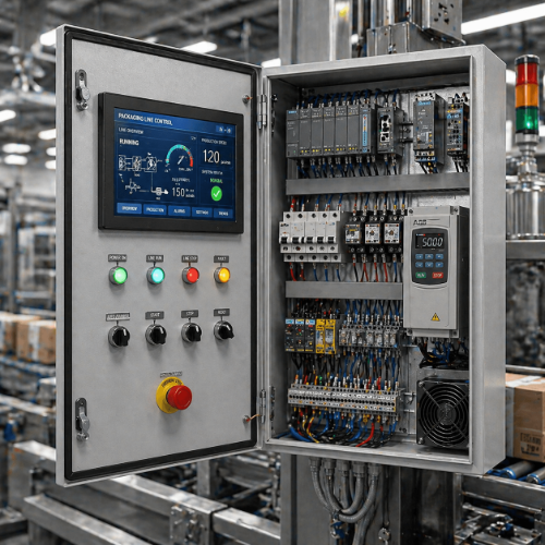
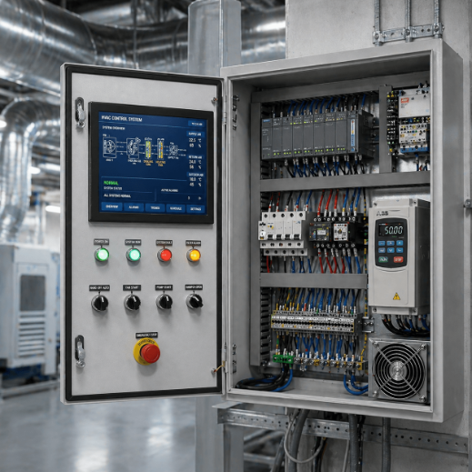
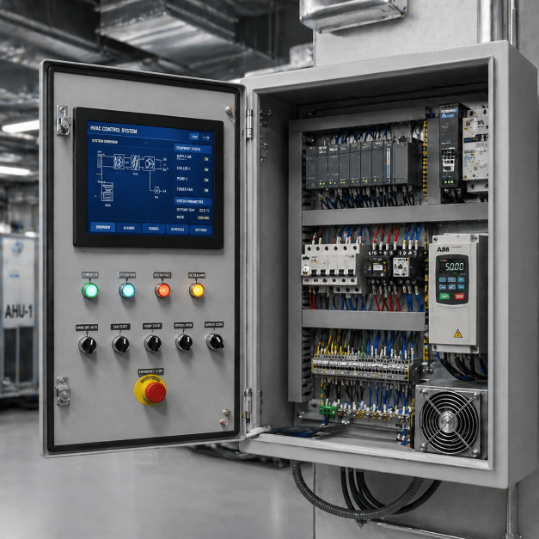
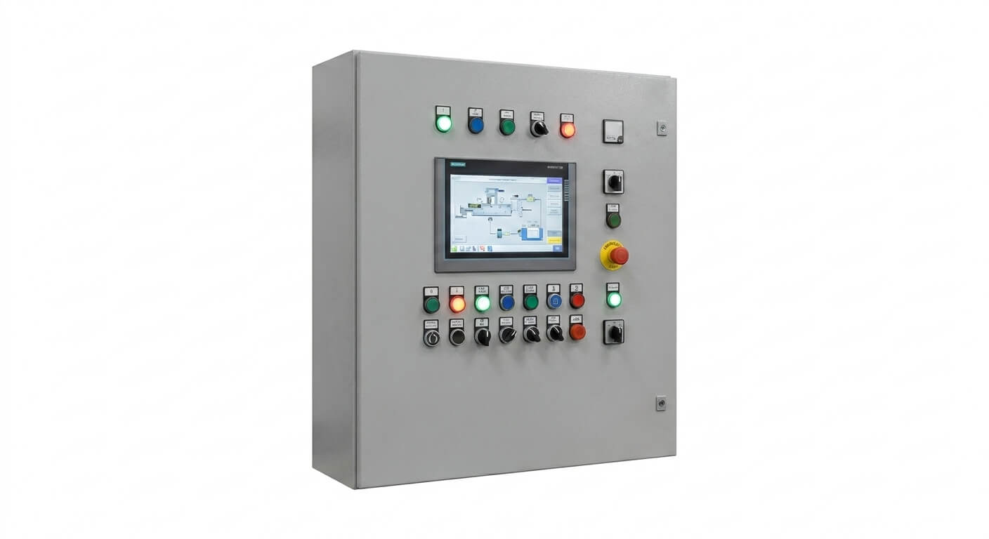
HVAC Control Panels
HVAC Control Panel Supplier
Custom HVAC control panels for AHUs, ventilation fans, pumps, cooling towers and chiller plants. Send sequence, motor schedule, sensors and BAS/BMS points.
Specifications
- Application
- HVAC & Building Automation
- Control Method
- PLC / Relay Based
- Supported Protocols
- Modbus, BACnet, Ethernet/IP
- Power Supply
- 220V / 380V / 480V
- Protection Rating
- IP54 / IP65 Optional
- Enclosure Material
- Carbon Steel / Stainless Steel
- Customization
- Available
- Testing
- FAT Before Shipment
Quick Answer
An HVAC control panel sequences and protects your heating, cooling, ventilation and pumping equipment from one enclosure. UniRegal configures it to your mechanical design - AHU, chiller, boiler, fan or pump control - using the controller you specify. Built with a ~15-day lead time; UL 508A is available.
Product Positioning:
Project-specific HVAC control panels that coordinate mechanical equipment, field devices, local controls and BAS/BMS interfaces.
HVAC Control Panels Designed for Equipment Sequences and BMS Integration
An HVAC control panel should translate the mechanical design into a clear operating sequence. It must coordinate fans, pumps, dampers, valves, sensors and VFDs while defining how local control, BAS/BMS commands, equipment protection and emergency interfaces work together.
UniRegal supplies custom HVAC control panels for:
- Air handling units
- Supply and return fans
- Exhaust and ventilation systems
- Chilled-water and condenser-water pumps
- Cooling towers
- Chiller plant auxiliaries
- Commercial mechanical rooms
- Industrial ventilation systems
- Building automation projects
- Existing HVAC control retrofits
Control options: Relay, DDC, PLC and VFD
BAS/BMS interfaces: BACnet, Modbus or hardwired signals
Project basis: Mechanical schedule, sequence, point list and field-device schedule
Verification: Drawing review, simulated sequence testing and interface checks
Quick Answer: What Is an HVAC Control Panel?
An HVAC control panel operates and monitors heating, ventilation and air-conditioning equipment according to an approved sequence. It receives temperature, pressure, humidity, airflow and equipment-status signals, then controls fans, pumps, dampers, valves and auxiliary devices while exchanging commands and status information with the BAS or BMS.
The correct panel cannot be selected from motor power alone. Buyers should first confirm:
- Which HVAC equipment the panel controls
- Which controller owns the operating sequence
- Which sensors and actuators connect to the panel
- Which protective and emergency signals must remain hardwired
- Which information is exchanged with the BAS/BMS
- What the equipment should do if communication fails
- Which functions are tested at the factory and at the site
Buyer Decision Information
Choose the Panel According to the Control Responsibility
Project Requirement | Suitable Panel Direction | Main Decision |
|---|---|---|
One AHU with complete local control | AHU control panel | Full AHU sequence and BMS interface |
Several basic ventilation fans | Fan control panel | Start source, proof signal and emergency shutdown |
Variable-speed fan or pump | HVAC VFD panel | Control signal, feedback and fallback operation |
HVAC equipment controlled by a building controller | DDC control panel | Controller platform, point list and network |
Existing equipment connected to a new BMS | BAS/BMS interface panel | Gateway, data mapping and control authority |
Pumps, cooling towers and chiller auxiliaries coordinated together | Chiller plant control panel | Equipment staging and OEM interfaces |
Existing building with obsolete controls | Retrofit HVAC control panel | Reused devices, shutdown plan and migration scope |
A BACnet-compatible controller does not automatically create a working HVAC system. The operating sequence, device points, read/write permissions, alarms, setpoints and local response to network failure must still be defined.
The First Procurement Question: Who Controls What?
HVAC projects often involve a mechanical contractor, equipment supplier, control-panel builder, BMS contractor, electrical contractor and fire-alarm contractor. Commissioning problems appear when two parties assume that the other party owns a command or signal.
Typical Responsibility Matrix
Function | Responsibility to Confirm |
|---|---|
HVAC equipment sizing | Mechanical designer or equipment supplier |
Airflow and hydronic design | Mechanical designer |
Mechanical sequence of operation | Consulting engineer, OEM or mechanical designer |
Panel electrical design | Control-panel supplier |
Local controller programming | Panel supplier or BMS contractor |
BAS/BMS supervisory programming | BMS contractor |
Field sensor and actuator selection | Mechanical, controls or equipment supplier |
Field installation and cabling | Electrical or controls contractor |
Fire-alarm signal source | Fire-alarm contractor |
Approved emergency response | Fire-protection engineer or authority |
Air and water balancing | TAB contractor |
Final control-loop tuning | Controls commissioning team |
Functional performance testing | Commissioning authority or agreed project party |
The quotation should state whether UniRegal supplies a wired panel only, a panel with programmed controls, or a complete local control package with BMS interface points.
The Four Documents That Define an HVAC Control Panel
1. Mechanical Equipment Schedule
The schedule identifies fan, pump, AHU, cooling-tower and auxiliary loads, together with voltage, motor rating, starter type, VFD requirement and equipment operating duty.
2. Sequence of Operation
The sequence explains how equipment starts, modulates, stages, stops and responds to abnormal conditions. It should also define occupied, unoccupied, manual and emergency modes where applicable.
3. Controls Point List
The point list identifies every input, output and network point, including signal type, engineering units, alarm requirement and read/write authority.
4. Controls Schematic
The schematic shows how controllers, sensors, dampers, valves, VFDs, equipment panels, BMS networks and emergency interfaces are connected.
When these documents are incomplete, assumptions should be recorded and approved before panel production.
AHU Control Panel Sequence
An AHU control panel normally coordinates the supply fan, return or exhaust fan, outdoor-air damper, return-air damper, heating and cooling valves, filters, sensors and BMS interface.
The sequence must match the actual AHU arrangement. A constant-air-volume unit, variable-air-volume unit, fresh-air unit and process ventilation unit should not receive the same generic program.
Typical AHU Start Sequence
1. Receive the Enable Command
The command may originate from an occupancy schedule, local selector, BMS request, process interlock or another approved source.
2. Check Start Permissives
Before starting the fan, the controller checks the project-defined conditions. These may include fan availability, emergency shutdown status, damper status, freeze-protection device and external equipment permissives.
3. Position Dampers
Outdoor, return and exhaust dampers move to the required starting positions. Where position proof is specified, the sequence waits for confirmation before continuing.
4. Start the Fan
The panel starts the fan through a contactor or VFD. A start command alone does not prove airflow.
5. Confirm Fan or Airflow Status
Fan proof may be obtained from a differential-pressure switch, airflow switch, current sensor, auxiliary contact, VFD status or a project-defined combination.
6. Enable Temperature Control
Heating, cooling, economizer, humidification or dehumidification control begins only after the required airflow or fan status is established.
7. Report Operating Status
The panel makes the approved run status, mode, alarms, temperatures, pressures, VFD data and setpoints available to the local display or BMS.
Typical AHU Stop Sequence
The stop sequence may disable heating, cooling or humidification before stopping the fan, then move dampers to their approved shutdown positions. The required order depends on the mechanical design, climate and equipment supplier’s requirements.
CAV and VAV Air-System Control
Constant Air Volume
A constant-air-volume system normally operates at a fixed airflow. The control panel may use fixed-speed starting or a VFD with a defined operating command, depending on the system design.
The principal control loop often focuses on supply-air temperature, space temperature or another project-specific variable.
Variable Air Volume
A variable-air-volume system changes supply airflow according to zone demand. Fan speed may be controlled from duct static pressure, airflow or a supervisory reset strategy.
The buyer should confirm:
- Static-pressure sensor location
- Pressure measurement range
- Initial setpoint
- Minimum and maximum fan speed
- High-static-pressure response
- VAV terminal feedback available to the controller
- Static-pressure reset method
- Response if the pressure signal fails
- BMS authority to change the setpoint
A VFD does not determine the correct static-pressure target by itself. The sensor location, control limits and reset strategy must come from the approved HVAC design.
Temperature and Humidity Control
Temperature control may involve heating valves, cooling valves, electric heaters, DX stages, compressors or equipment commands. Humidity control may involve humidifiers, cooling and reheat sequences, or other project-defined equipment.
Information Required for Each Control Loop
Control Detail | Required Definition |
|---|---|
Controlled Variable | Supply-air, return-air, room temperature or humidity |
Sensor Location | Duct, room, coil or equipment location |
Measurement Range | Approved sensor range |
Setpoint Source | Fixed, local adjustable, schedule or BMS |
Controlled Output | Valve, damper, heater, stage or speed command |
Minimum and Maximum Output | Equipment operating limits |
Deadband | Permitted range before corrective action |
Alarm Limits | High, low or deviation alarm |
Signal Failure Response | Stop, fixed output, fallback sensor or alarm |
Reset Authority | Local controller, BMS or authorized technician |
Final tuning depends on the installed coils, valves, dampers, sensors, airflow and building load. Factory testing can verify the logic but cannot complete final HVAC loop tuning.
Fan and Filter Monitoring
A reliable AHU sequence should distinguish between a fan command, fan running status and proven airflow.
Signal | Meaning |
|---|---|
Fan Command | The controller has requested operation |
Contactor Feedback | The starter contactor is energized |
VFD Running | The drive reports that it is running |
Motor Current | The motor is drawing current |
Airflow Proof | Air movement or duct pressure has been detected |
Fan Fault | The starter, drive or motor protection has tripped |
Filter condition may be monitored through a differential-pressure switch or transmitter. The alarm setpoint should match the filter and AHU design rather than using a universal value.
Freeze-Protection Response
In cold-climate AHU applications, freeze protection may involve a low-temperature detector, water-coil temperature sensor, outdoor-air temperature or another approved signal.
A project-specific response may include:
- Stopping the supply fan
- Closing the outdoor-air damper
- Opening the heating valve
- Starting an associated pump
- Disabling cooling
- Generating a latched alarm
- Requiring manual reset
The exact response must follow the mechanical sequence and applicable local requirements. The panel supplier should not invent freeze-protection logic from the words “low-temperature alarm.”
Chilled-Water and Condenser-Water System Coordination
An HVAC plant control panel may coordinate pumps, chillers, cooling towers, isolation valves and field sensors. It does not replace the chiller manufacturer’s internal controller.
Typical Plant Sequence Decisions
Decision | Information Required |
|---|---|
Plant Enable | Schedule, load request or operator command |
Valve Position | Required valves and position confirmation |
Pump Operation | Duty, standby, staging and flow-proof requirements |
Chiller Enable | Required pump, flow, valve and alarm permissives |
Additional Chiller Stage | Load, temperature, capacity or time criteria |
Cooling-Tower Operation | Chiller request, condenser temperature and staging |
Differential-Pressure Control | Sensor location, setpoint and reset method |
Equipment Rotation | Runtime, schedule or approved priority |
Low-Load Operation | Minimum equipment limits and shutdown criteria |
Power Restoration | Staged restart, delay or manual release |
Chiller, cooling-tower and VFD limits should be coordinated with the equipment suppliers. The plant panel should issue approved enable commands and monitor required feedback without overriding internal equipment protection.
BAS/BMS Integration: A Protocol Name Is Not Enough
BACnet and Modbus allow devices to exchange information, but successful integration requires a defined network and point schedule.
Communication Details to Confirm
Integration Item | Buyer Decision |
|---|---|
Protocol | BACnet or Modbus |
Network Type | BACnet/IP, BACnet MS/TP, Modbus TCP or Modbus RTU |
Controller Role | Local controller, gateway or BMS field controller |
Device Addressing | Device instance, MAC address, IP address or slave ID |
Baud Rate and Serial Settings | Required for serial networks |
Point Names | Agreed naming convention |
Engineering Units | °C, °F, Pa, bar, %, Hz or project units |
Point Direction | Read-only, commandable or locally controlled |
Setpoint Authority | Local panel, BMS or shared under defined conditions |
Alarm Ownership | Local panel, BMS or both |
Trend Responsibility | Controller or BMS |
Schedule Ownership | Local controller or BMS |
Communication Failure | Continue locally, fixed fallback or stop |
Gateway Scope | Required when protocols or devices differ |
Integration Testing | Factory simulation, site test or both |
A controller described as “BACnet ready” may still require device configuration, object mapping and site network integration. The quotation should define whether it includes only the communication hardware or complete panel-side point configuration.
Local Control After BMS Communication Failure
Many HVAC systems need to continue operating safely when the BAS/BMS network is unavailable.
The control philosophy should answer:
- Does the local panel continue its current schedule?
- Does it retain the last valid setpoint?
- Does it use a locally stored fallback setpoint?
- Are remote commands cleared after a timeout?
- Which alarms remain visible locally?
- Does the equipment stop if the BMS enable signal disappears?
- How does the panel reconnect without causing an unexpected restart?
For equipment requiring local autonomy, essential control loops and protection functions should reside in the local controller instead of depending entirely on continuous BMS communication.
Fire Alarm, Smoke Shutdown and Emergency Interfaces
HVAC control panels may receive fire-alarm shutdown, smoke-detector or emergency-ventilation commands. These signals require a clearly approved interface.
Ordinary HVAC shutdown and an engineered smoke-control system are not the same scope.
The project must define:
- Which system initiates the emergency command
- Whether the signal is hardwired or communicated
- Which fans stop
- Which fans continue or change mode
- Required damper positions
- Whether status feedback returns to the fire-alarm system
- Reset authority
- Required emergency power
- Acceptance-testing responsibility
The fire-protection engineer, authority having jurisdiction and approved life-safety documents determine the required sequence. UniRegal implements the confirmed interface but should not independently define smoke-control operation.
Sensors and Field Devices
Typical HVAC field devices may include:
Inputs
- Supply-, return- and outdoor-air temperature
- Room temperature and humidity
- Duct static pressure
- Filter differential pressure
- Chilled-water differential pressure
- Airflow or fan differential-pressure switch
- Flow switch
- Freeze-protection contact
- Damper position feedback
- Valve position feedback
- Smoke or fire shutdown contact
- VFD run and fault status
- Equipment available and common-fault contacts
Outputs
- Fan and pump start commands
- VFD speed reference
- Damper commands
- Modulating valve commands
- Heating or cooling enable
- Chiller and cooling-tower enable
- Alarm outputs
- BMS status and data points
Every point should identify the signal type, voltage, normal state, engineering range, cable destination and required control action.
Local, Automatic and Remote Modes
Local Manual Mode
Allows authorized operation from the panel during maintenance or commissioning. Equipment protection and approved emergency shutdowns should remain active unless the project documents explicitly state otherwise.
Local Automatic Mode
The panel follows its internal schedule, sensors, setpoints and operating sequence.
Remote or BMS Mode
The BMS provides approved enable commands, schedules or setpoints. The local controller continues to execute equipment-level sequence and protection functions.
Mode Indication
The active mode should be visible locally and reported to the BMS. Operators should not have to determine control ownership by trial and error.
Selecting DDC, PLC, Relay or VFD Control
Architecture | Suitable Application | Buyer Consideration |
|---|---|---|
Relay Control | Simple fan or equipment interlock | Limited diagnostics and sequence changes |
DDC Control | Building HVAC and BAS integration | Controller compatibility and BMS engineering tools |
PLC Control | Industrial HVAC or complex packaged systems | I/O, software and plant-system integration |
VFD Internal Control | Basic pressure, airflow or equipment control | Limited system-wide coordination |
DDC/PLC with VFD | AHU, pump or plant control | Clear ownership of the control loop |
BMS Interface Panel | Existing packaged equipment | Point mapping and command authority |
The correct architecture depends on the sequence and building integration requirement. A PLC is not automatically better than a DDC controller for a building HVAC application, and a DDC controller is not automatically suitable for every industrial system.
Rooftop, Mechanical-Room and Outdoor Installation
The installation environment affects the enclosure, component layout and thermal design.
Mechanical Rooms
The design should consider humidity, condensation, pipe leakage, maintenance access and the location of water lines above the panel.
Rooftop Installation
The enquiry should state ambient temperature, solar exposure, rain, dust, wind-driven moisture and cable-entry requirements.
Industrial Areas
Dust, process heat, vibration, washdown conditions or corrosive contaminants may require a different enclosure material and cooling approach.
An enclosure rating alone does not confirm that the internal equipment will remain within its operating temperature. VFD heat, solar loading, ventilation and condensation control should be reviewed together.
Retrofit HVAC Control Panels
Retrofit work requires more than copying the existing cabinet because field changes may not appear in the original drawings.
Information to Collect
- Existing panel photographs
- Electrical drawings
- Controller and VFD model numbers
- Available program backups
- Current BMS protocol
- Existing BMS point list
- Sensor and actuator details
- Motor and equipment nameplates
- Actual operating sequence
- Fire-alarm and emergency interfaces
- Available shutdown period
- Equipment that must remain operational
Retrofit Decisions
The buyer should confirm whether the project requires:
- Like-for-like panel replacement
- Controller migration
- VFD replacement
- Conversion from relay or pneumatic control
- Retention of existing sensors and actuators
- Addition of BACnet or Modbus
- Revised sequence or setpoints
- New BMS graphics and trends
- Phased changeover
- Temporary manual operation
Existing building operation should be documented before disconnection. A new panel cannot reproduce undocumented control behavior from photographs alone.
Factory Acceptance Testing for HVAC Control Panels
HVAC FAT should test the approved sequence and interfaces rather than only verifying electrical continuity.
Typical FAT Scope
- Component and BOM verification
- Wiring, grounding and terminal checks
- Controller hardware and I/O checks
- Analog-signal injection and scaling
- AHU startup and shutdown simulation
- Fan command, feedback and airflow-proof testing
- Damper command and feedback simulation
- Valve-output checks
- Temperature, pressure and humidity loop response
- Freeze-protection input simulation
- Filter-alarm simulation
- VFD command, reference and feedback checks
- Local/manual/automatic mode checks
- BMS point verification
- Communication-loss response
- Fire-alarm interface simulation according to the approved matrix
- Alarm text, delay and reset checks
- Power-restoration response
- Software and parameter backup
What FAT Can Verify
Factory testing can verify panel wiring, I/O scaling, command logic, operating modes, alarm actions and panel-side communication points using simulated field signals.
What FAT Cannot Fully Verify
Factory testing cannot reproduce actual building airflow, hydronic balance, duct static behavior, thermal load, sensor placement, valve authority, room conditions or the live BMS network. It also does not replace TAB, final PID tuning, integrated systems testing or life-safety acceptance.
These activities should be assigned separately before the project begins.
Documentation for Approval and Handover
Depending on the agreed scope, the documentation package may include:
- General arrangement drawing
- Electrical schematic
- Panel layout
- Bill of materials
- I/O list
- Terminal schedule
- Field connection diagram
- HVAC sequence of operation
- Cause-and-effect matrix
- BAS/BMS point list
- Network architecture
- Alarm and interlock list
- Controller hardware configuration
- VFD parameter record
- Program and configuration backups
- FAT checklist or test report
- Operation and maintenance information
The revision status of drawings, program and point list should match the panel configuration shipped.
How to Compare HVAC Control Panel Quotations
Quotation Item | Question to Ask |
|---|---|
Sequence | Is the approved HVAC sequence included in programming? |
Control Boundary | Who controls the AHU, plant equipment and BMS functions? |
Field Devices | Are sensors and actuators included or interfaces only? |
VFD Scope | Are drives, bypass, communications and parameters included? |
BMS Integration | Does the price include hardware only or point configuration? |
BACnet/Modbus | Which network type and device configuration are included? |
Point List | Are all physical and network points counted? |
Emergency Interface | Which approved shutdown signals are included? |
Local Autonomy | What happens when BMS communication fails? |
HMI | Are local display, alarms and editable setpoints included? |
Documentation | Which drawings, schedules and software backups are supplied? |
FAT | Is the sequence simulated or is testing limited to wiring? |
Site Work | Are installation, TAB, commissioning and BMS graphics included? |
Certification | Which electrical or project standard is confirmed? |
This comparison prevents a basic starter enclosure from being evaluated against a complete AHU or plant automation panel as though both quotations covered the same work.
Typical Technical Configuration
All values and brands are selected according to the approved project requirements.
Item | Project-Defined Options |
|---|---|
Application | AHU, fans, pumps, chiller plant, cooling tower or ventilation |
Control Architecture | Relay, DDC, PLC or VFD |
Power Supply | Project-defined voltage, phase and frequency |
Motor Starting | Contactor, overload relay, soft starter or VFD |
Field Signals | Dry contact, analog, pulse or communication |
BAS/BMS Protocol | BACnet, Modbus or hardwired I/O |
Local Interface | Selector switches, indicators or HMI |
Installation | Mechanical room, rooftop, outdoor or industrial area |
Enclosure | Wall-mounted or floor-standing |
Environmental Protection | Project-defined IP or NEMA requirement |
Documentation | Drawings, point list, terminal list, logic and test records |
Testing | Electrical inspection, I/O verification and sequence FAT |
Applicable assembly standards, short-circuit ratings, enclosure approvals and third-party certification must be specified in the enquiry and confirmed in the quotation.
Information Required for Quotation
HVAC Equipment
- AHU, fan, pump, chiller or cooling-tower schedule
- Motor voltage, phase, power and full-load current
- Starting and speed-control method
- Equipment supplier and model where available
- Simultaneous-running requirements
Control Sequence
- Occupied and unoccupied modes
- Start and stop sequence
- CAV or VAV operation
- Temperature and humidity control
- Fan and airflow proof
- Damper and valve sequence
- Freeze-protection response
- Equipment staging
- Power-restoration response
- Emergency shutdown requirement
Field Devices
- Temperature and humidity sensors
- Pressure and differential-pressure sensors
- Airflow and flow switches
- Dampers and actuators
- Control valves and actuators
- Emergency and equipment-status contacts
- Signal types and measurement ranges
BAS/BMS
- Protocol and network type
- Point list
- Controller preference
- Network addressing requirements
- Read/write permissions
- Schedule and setpoint ownership
- Alarm and trend responsibility
- Communication-failure response
- Gateway requirements
Installation
- Panel location
- Ambient temperature
- Humidity and condensation
- Outdoor exposure
- Enclosure material
- Protection rating
- Mounting and cable-entry requirements
Deliverables
- Required drawings
- Software handover
- FAT procedure
- Certification requirement
- Site commissioning scope
- Delivery schedule
Frequently Asked Questions
What is the difference between an HVAC control panel and a BMS control panel?
An HVAC control panel directly operates specific equipment such as an AHU, fan, pump or cooling-tower system. A BMS panel or server supervises multiple building systems. The project must define which controller owns schedules, setpoints, operating logic and alarms.
Who should write the HVAC sequence of operation?
The sequence is normally developed or approved by the mechanical designer, equipment supplier or consulting engineer. The panel programmer implements that approved sequence. If sequence development is included in the panel scope, the responsible mechanical party should still review it before production.
Does BACnet compatibility guarantee connection to our BMS?
No. BACnet compatibility establishes a communication method, but integration still requires the correct network type, device addressing, point mapping, units, read/write permissions, alarm handling and site testing. A gateway may also be required when existing devices use another protocol.
Can the AHU continue operating if BMS communication is lost?
Yes, when local autonomous operation is specified. The local controller can retain schedules or use fallback setpoints, but the exact response must be approved. Equipment should not depend on an undefined network connection for essential control and protection.
How should fire-alarm shutdown be connected?
The approved fire and life-safety documents must define the initiating signal, wiring method, affected fans and dampers, reset procedure and required feedback. The HVAC panel should implement this confirmed interface without independently deciding the emergency sequence.
Is an airflow switch still needed when the VFD provides a running signal?
A VFD running signal confirms drive operation but does not always prove airflow. Whether additional airflow or differential-pressure proof is required depends on the mechanical sequence and the consequence of operating heating, cooling or humidification without airflow.
Does every HVAC VFD panel need a bypass starter?
No. Bypass may help some critical applications continue at fixed speed after a drive fault, but it adds equipment, enclosure space and operating considerations. The decision should be based on continuity requirements, motor suitability and the approved mechanical sequence.
Should we use a PLC or DDC controller for HVAC?
DDC is commonly selected for building automation and direct BMS integration. PLC control may be more appropriate for industrial HVAC, packaged equipment or complex plant integration. The decision should consider the installed BMS, programming support, I/O and long-term maintenance.
Can factory testing verify room temperature and airflow performance?
No. FAT can verify sequence logic, I/O, commands, alarms and communication using simulated signals. Actual airflow, hydronic balance, temperature control and pressure stability require field sensors, operating equipment, TAB and site commissioning.
Can you replace an HVAC panel if the original drawings are missing?
A replacement is possible, but photographs alone are insufficient. The existing equipment, field wiring, sensors, actuators, BMS points, emergency interfaces and actual sequence should be surveyed before the new panel design is approved.
What should be included in the BMS point list?
The list should include point name, type, units, source, network address, read/write status, alarm requirement, trend requirement, update method and operating purpose. It should also state which system owns each command and setpoint.
What information is needed for an HVAC control panel quotation?
Please send the mechanical equipment schedule, motor list, sequence of operation, controls schematic, field-device schedule, BAS/BMS point list, protocol, panel location and applicable project requirements. Existing-panel photos and program information are also useful for retrofit projects.
Request an HVAC Control Panel Quotation
Send UniRegal your HVAC equipment schedule, motor list, sequence of operation, controls schematic, field-device schedule and BAS/BMS point list.
We review the equipment sequence and control boundary before finalizing the panel configuration. This allows the proposal to define local controls, BMS interfaces, emergency signals, documentation and FAT scope instead of providing only a cabinet price.
We confirm receipt within 24 hours and advise the next technical step within 1–2 business days, depending on project complexity.
Related Industrial Page:
If the panel has to talk to a building management system, that protocol belongs in the enquiry — see integrating HVAC panels into a modern BMS and custom control panels .