
Jul 14, 2026Case Studies
Why Is Your PID Loop Unstable—and Why PID Tuning May Not Be the Real Solution?
Unstable PID loops are often caused by noisy signals, poor grounding, valve deadband, or sensor delays—not bad tuning. Check the process before changing controller settings.
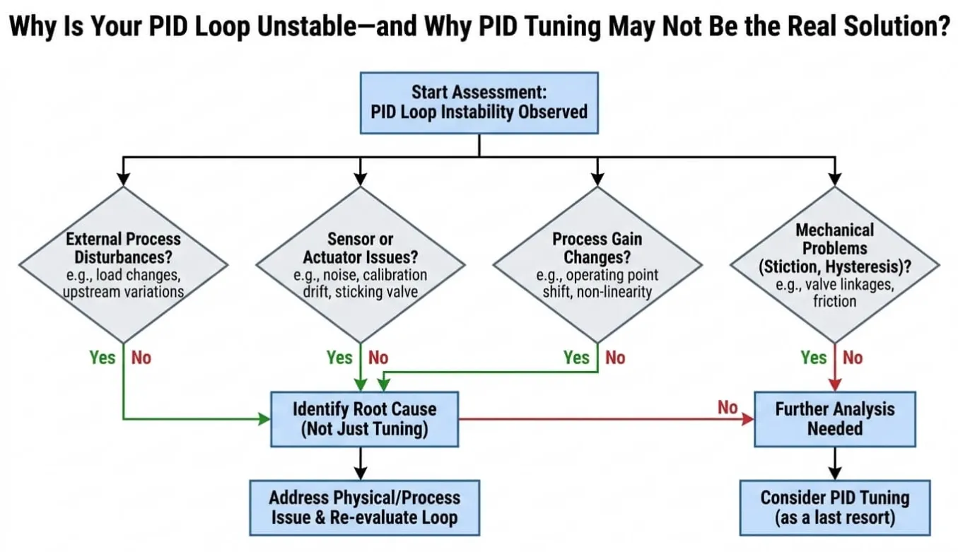
When a PID loop starts hunting, the PLC usually becomes the first suspect. Engineers open their laptops, operators watch the trend screen, and someone begins changing the P and I values. Several hours later, the pressure is still moving. The real problem may have been sitting inside the cabinet or piping system all along.
In my experience, many unstable PID control loops[¹] are not caused by poor programming. The controller may simply be responding to information that does not reflect the real process. VFD interference[²] can distort an analog reading, a worn actuator may ignore small commands, and poor sensorplacement[³] can create a delay that no ordinary tuning method can fully correct. Before I touch the PID settings, I put the loop in manual mode[⁴] and check what is actually happening in the field.
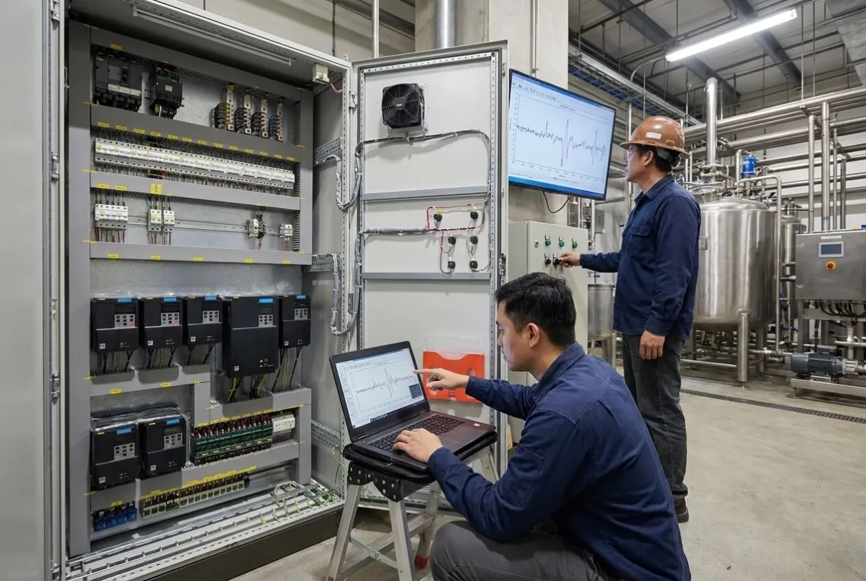
I learned this lesson on an industrial wastewater reuse project where three engineers spent several days tuning a pressure loop that was never broken. In the end, a correctly installed shield clamp solved what repeated software adjustments could not.
Why Did a Stable Pump Look Unstable on the HMI?
The system used a high-pressure pump, a VFD, a pressure transmitter, and a PLC. On the drawings, it was a standard closed-loop pressure control system, and there was nothing unusual about the design.
During commissioning, however, the HMI trend moved constantly. The VFD frequency followed the changing pressure value, and the pump repeatedly accelerated and slowed down. Because the behavior looked like classic PID hunting, the site team assumed the controller needed retuning.
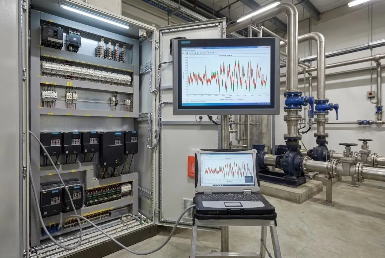
They reduced the proportional gain[⁵], changed the integral time[⁶], added filtering, and tested both conservative and aggressive settings. Each adjustment changed the shape of the trend, but none of them removed the instability.
The pressure spikes eventually became serious enough for the operator to stop the RO skid[⁷]. That was a sensible decision because repeated pressure shocks can place unnecessary stress on reverse osmosis membranes[⁸], seals, piping, and high-pressure pumps[⁹].
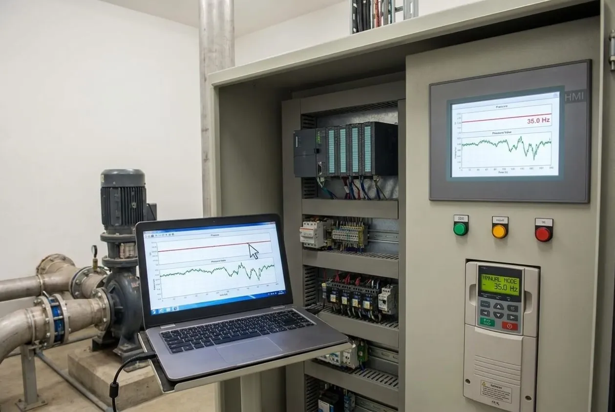
One of our senior engineers then suggested switching the loop to manual mode and holding the VFD at 35 Hz. The pump immediately ran smoothly, and the discharge pipe stopped shaking, yet the pressure value displayed by the PLC continued to move.
That result changed our diagnosis. The process itself was stable, which meant the controller was reacting to an inaccurate reading rather than correcting a genuine pressure problem.
!
How Can VFD Interference Affect a 4–20 mA Reading?
A variable frequency drive controls motor speed through high-frequency switching. This makes VFDs extremely useful, but the output cable can also become a strong source of electromagnetic interference when cabinet layout and grounding are handled poorly.
When we inspected the cabinet, we found that the pressure transmitter cable had been routed beside the 480 V VFD output cable. The wiring looked neat, but the arrangement allowed the low-level instrumentation circuit to pick up interference from the motor cable.
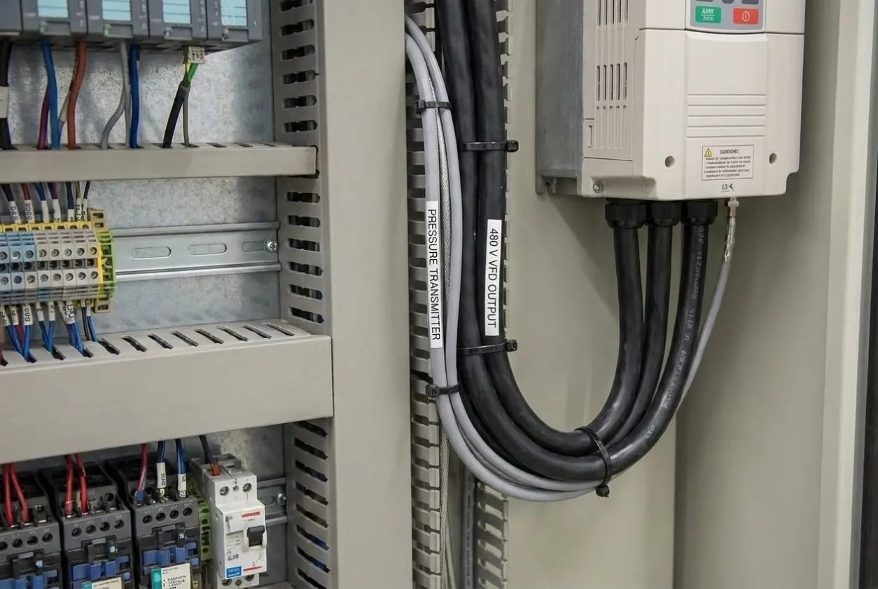
The transmitter used a 4–20 mA analog loop, which should have given the PLC a stable pressure value. Instead, the cable was carrying electrical disturbance into the analog input, so the controller responded to changes that were not occurring inside the pipe.
This is why I hesitate when someone immediately blames the PLC. The program may be following its instructions perfectly, but no control algorithm can make good decisions when the value entering the calculation is unreliable.
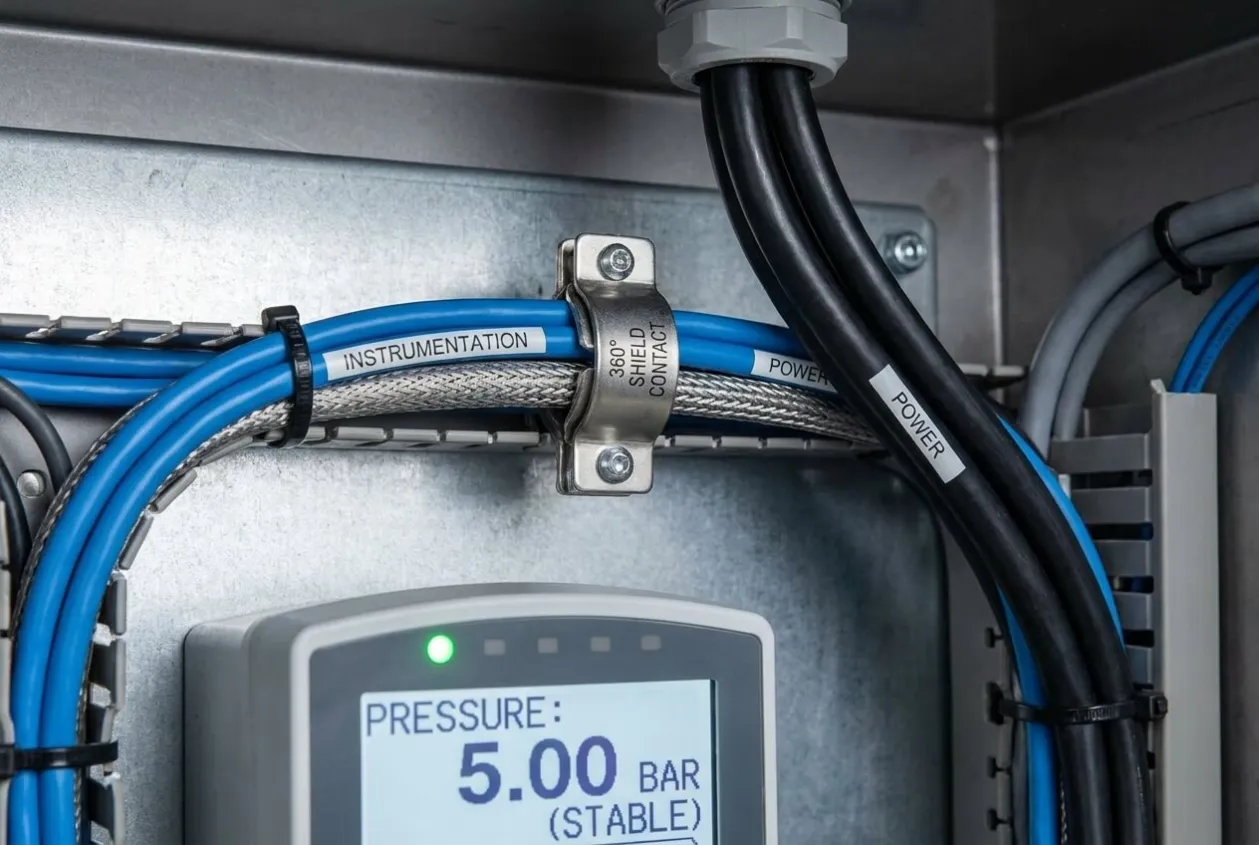
We separated the instrumentation wiring from the power cable and installed a proper EMC shield clamp with full 360-degree contact. Once the shield termination and cable routing were corrected, the pressure reading settled almost immediately.
We did not replace the PLC, rewrite the program, or install a more expensive transmitter. A small grounding component helped protect an RO system worth roughly $50,000, which is a useful reminder that industrial automation does not always reward the most complicated answer.
Why Is Manual Mode Such a Useful Diagnostic Test?
Manual mode temporarily removes the PID calculation from the control action. By holding the output at a fixed value, we can observe whether the physical process remains stable and whether the instrument reading accurately follows that condition.
When the pump runs smoothly in manual mode but the measured value continues to jump, I stop adjusting the PID parameters. At that point, I inspect the transmitter, loop power, cable routing, terminals, grounding, analog input channel, and nearby sources of interference.
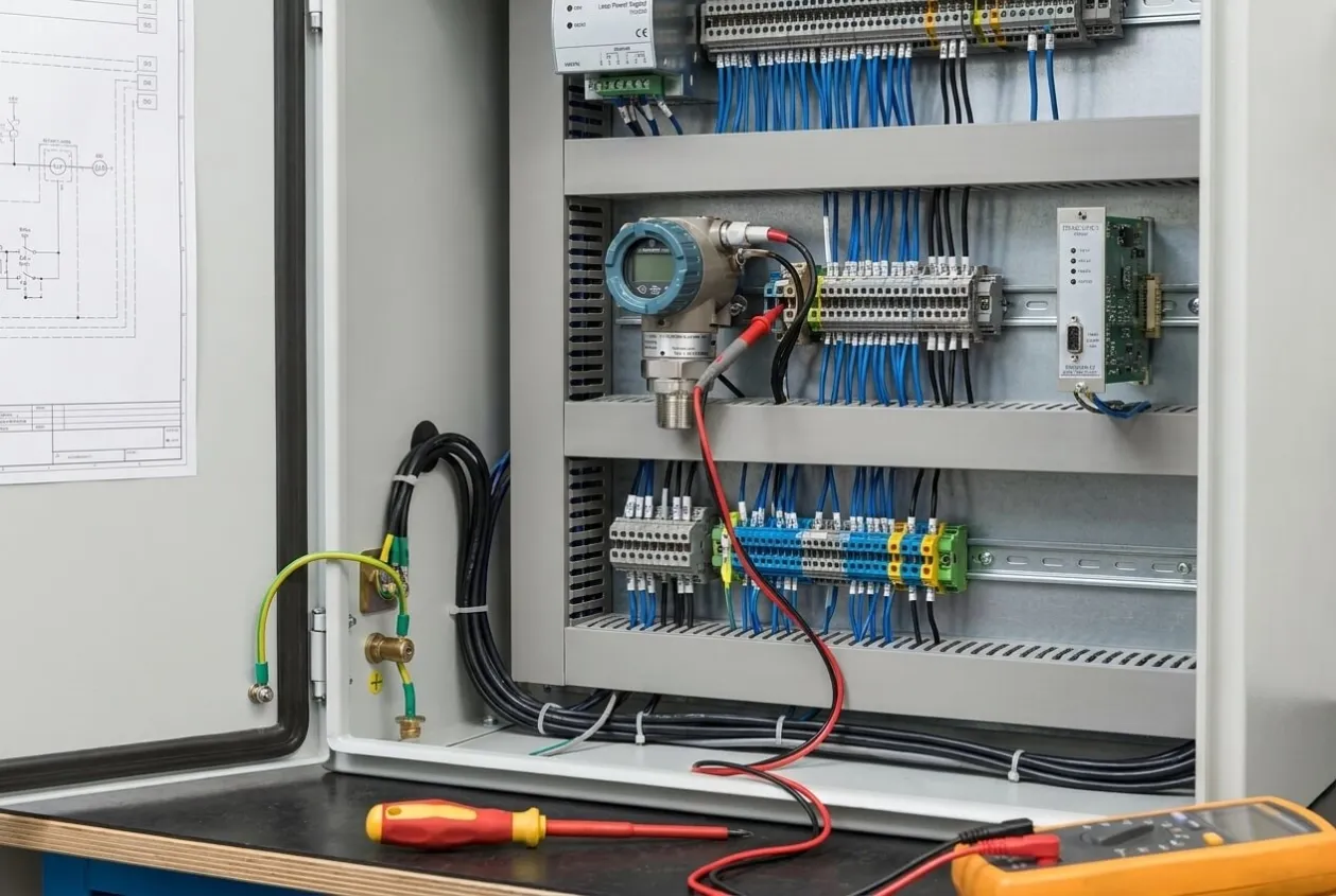
When the process and the reading both become stable in manual mode, tuning may be part of the problem. Even then, I still consider changing loads, nonlinear process behavior, equipment sizing, and whether PID control is the right strategy for the application.
This simple test prevents random parameter changes. I have seen enough commissioning teams adjust one value after another until nobody remembers the original settings, which creates more confusion without improving the diagnosis.
Can Valve Deadband Make a Correctly Programmed Loop Hunt?
Yes. Mechanical deadband occurs when a valve or actuator does not respond to small output changes. The controller keeps increasing its command because the process has not moved, and the actuator eventually breaks free with a much larger movement than intended.
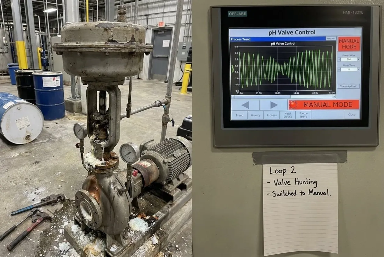
We saw this on a chemical dosing skid used for pH adjustment. The PLC requested a small valve correction, but the actuator did not respond. After several additional corrections, the valve moved suddenly and delivered too much chemical.
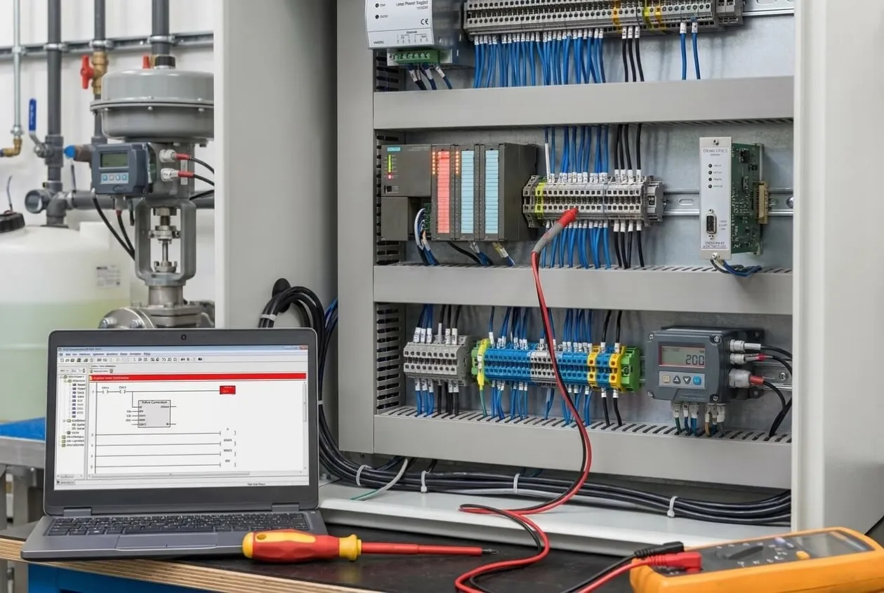
The pH crossed the target, so the controller reversed its command and started the same cycle in the opposite direction. The program was calculating a reasonable response, but the valve could not reproduce that response mechanically.
Increasing the proportional gain would have made the problem worse because the controller would have reacted more aggressively to equipment that was already moving unpredictably.
We inspected the actuator, slowed the control action, and added a small PID deadband so the program would not chase insignificant changes around the setpoint. The loop became calmer, and chemical consumption became more consistent.
This matters beyond control performance. A loop that hunts can accelerate valve wear, increase chemical usage, place more stress on pumps, and make operators lose confidence in automatic mode. Once operators routinely switch a loop to manual control, the system may still be running, but the automation has stopped doing its job.
How Does Sensor Placement Create Process Dead Time?
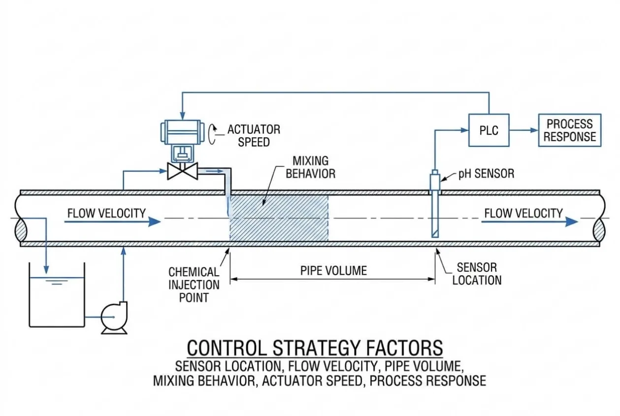
Process dead time is the delay between a control action and the moment its effect reaches the sensor. When that delay becomes too large, the controller is forced to make decisions without seeing the result of its previous corrections.
On another dosing project, the chemical injection point was located about 20 meters upstream from the pH sensor. The chemical needed almost 30 seconds to travel through the pipe before the instrument could detect the change.
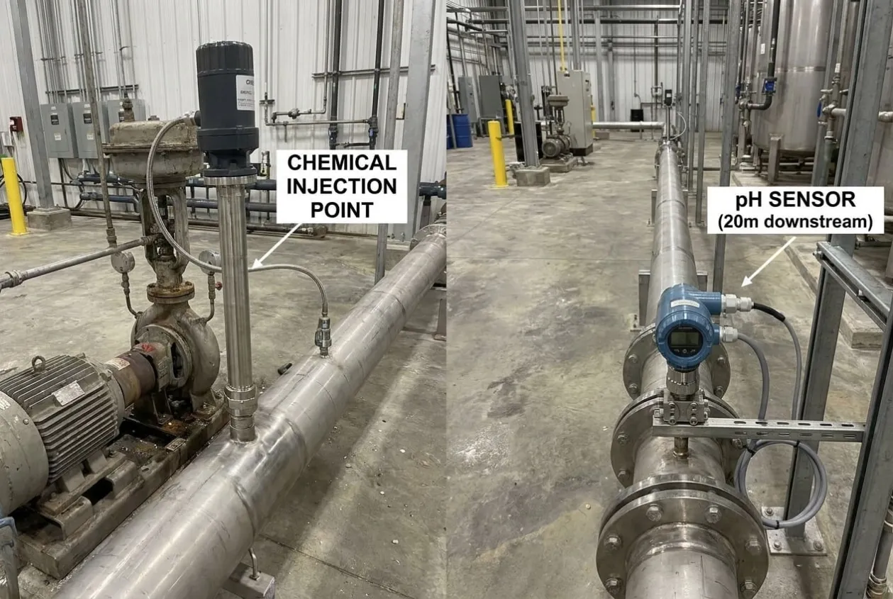
During that delay, the controller continued to add chemical because the measured pH had not yet responded. By the time the first dose reached the sensor, several more corrections were already moving through the pipe, which caused the process to overshoot.
The controller then reduced the output too far, and the system moved into a repeating cycle of overdosing and underdosing. Changing the PID values could reduce the severity, but it could not remove the transport delay created by the piping layout.
The correct solution may involve relocating the sensor[¹0], improving mixing, reducing the travel distance, or applying a more suitable dead-time compensation[¹1] strategy. That decision has to come from an understanding of the process, not from the controller manual alone.
This is why we review sensor location[¹2], flow velocity[¹3], pipe volume[¹4], mixing behavior, actuator speed[¹5], and process response[¹6] before finalizing a control strategy. A PLC can only control the process it has been given; it cannot redesign the pipe after commissioning starts.
What Should Buyers Check Before Ordering a Control Panel?
I advise buyers not to judge a control system only by the PLC brand. Siemens, Mitsubishi, Omron, Schneider Electric, ABB, and Allen-Bradley all make capable products, but premium hardware will still perform poorly when it is installed in a badly designed cabinet.
A serious panel supplier should be able to explain how analog and power cables are separated, how shields are terminated, how grounding paths are designed, and how sensitive circuits are checked before shipment.
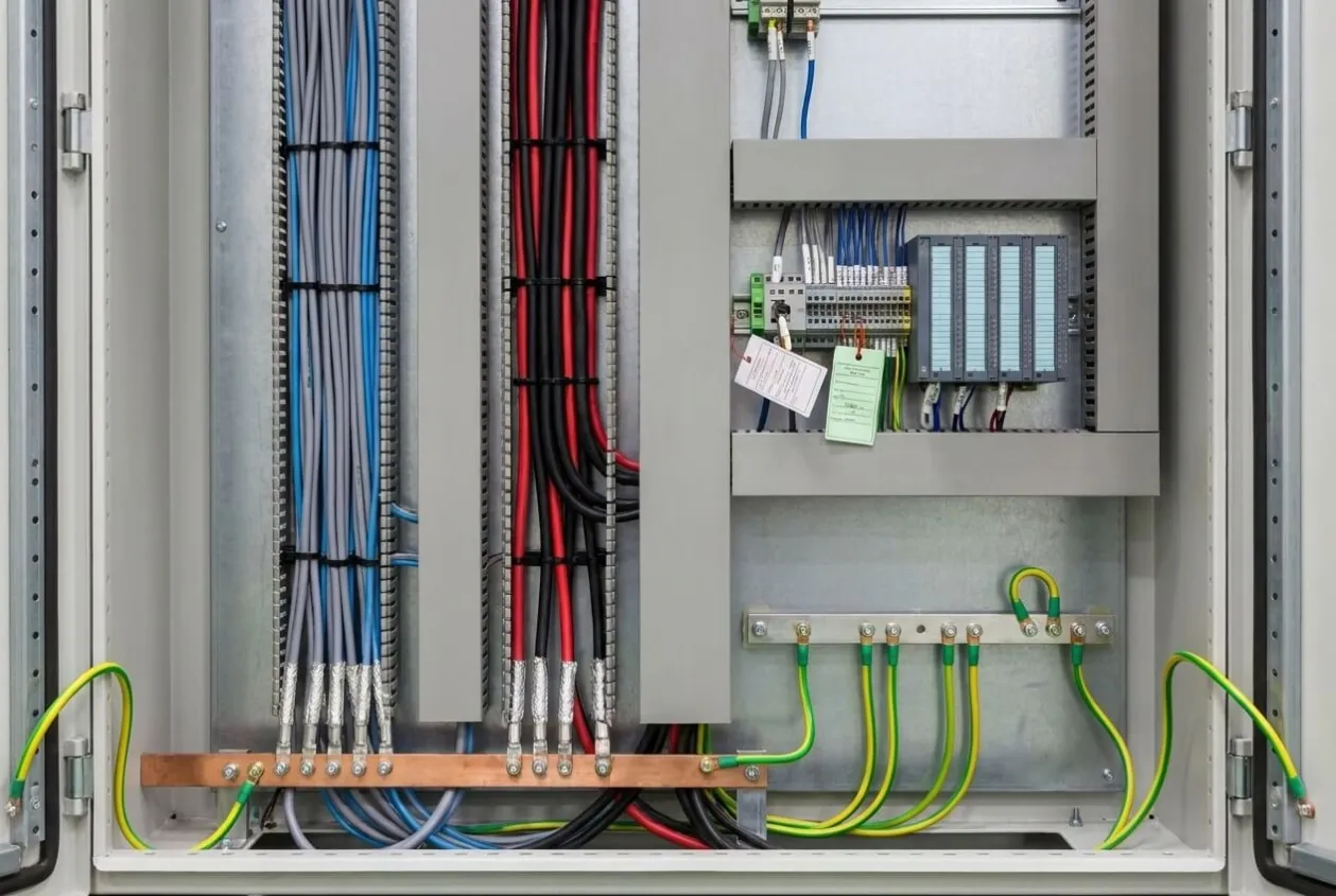
The supplier should also understand how the cabinet interacts with the field equipment. When a valve sticks, a transmitter is installed in the wrong place, or a motor cable interferes with an analog input, the customer needs more than a replacement part number.
At UniRegal, we supply PLCs, HMIs, VFDs, servo systems, relays, breakers, and other industrial automation components. However, I do not believe replacing hardware should be the first response to every unstable process.
Sometimes a customer genuinely needs a new analog module or transmitter. In other cases, the real solution is better cable routing, a corrected shield connection, or an actuator that can respond properly to small commands.
Knowing the difference saves more than component cost. It reduces commissioning delays, avoids unnecessary replacements, and helps prevent the kind of late-night site call that nobody enjoys receiving.
More Related Questions
Should I tune the PID before checking the wiring?
No. First confirm that the process value is accurate and stable. Tuning a controller around a distorted measurement usually hides the fault rather than solving it.
Can software filtering remove VFD interference?
Filtering may make the trend look calmer, but it cannot correct poor cable routing or grounding. Excessive filtering can also delay the measurement and make the controller slower to respond.
Should a cable shield be grounded at both ends?
The correct method depends on the equipment, grounding system, cable length, and frequency involved. Always review the manufacturer’s shield grounding guidance and evaluate the full EMC design.
How can I check whether a pressure transmitter is accurate?
Compare the PLC reading with a calibrated reference instrument under stable operating conditions. Then inspect the loop power, wiring, terminal connections, grounding, and analog input channel.
Can an old valve cause PID oscillation?
Yes. Friction, backlash, poor positioner performance, slow actuators, and oversized valves can all make a control loop unstable, even when the program is correct.
What is the best order for PID troubleshooting?
I begin by placing the loop in manual mode and holding the output steady. Then I compare the real process with the measured value, inspect the actuator, review the process delay, and adjust the PID settings only after the equipment and measurement have been verified.
Conclusion
Stable PID control begins with an honest view of the process. Reliable measurements, suitable equipment, correct grounding, and sensible sensor placement usually matter more than another round of parameter changes.
Whenever someone tells me the PID needs tuning, my first question is never about the controller. It is always about what the controller is actually seeing.
Related Articles: