
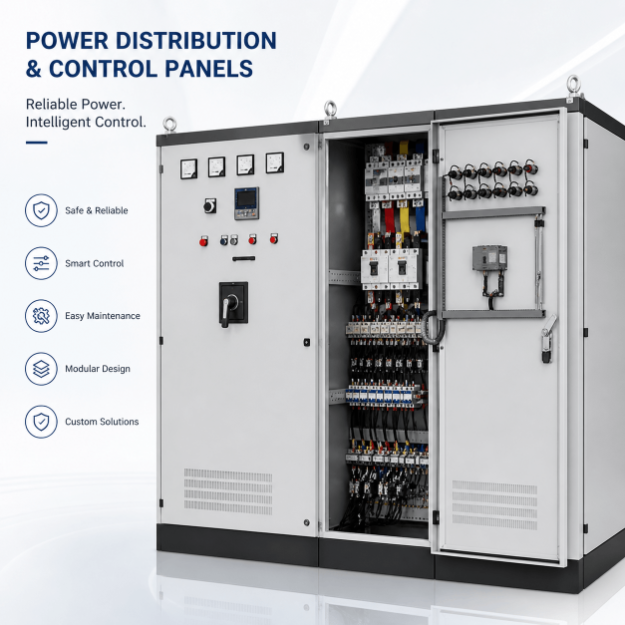
Power Distribution Panels
Power Control Panel Supplier
UniRegal supplies custom power control panels for industrial equipment groups that need protected distribution, switching, metering, alarms and interlocks. Send your load schedule, SLD, fault current and FAT scope.
Specifications
- Application
- Custom Industrial Automation
- Control Method
- PLC / Relay Based
- Voltage
- 220V / 380V / 480V Available
- Protection Rating
- IP54 / IP65 Optional
- Communication Protocol
- Modbus / Profinet / Ethernet/IP
- Testing
- FAT Before Shipment
- Customization
- Available
Quick Answer
A power control panel manages switching, protection and distribution of electrical power for your process - continuous, batch or hybrid. UniRegal configures it to your single-line diagram with multi-brand breakers, contactors and relays, ~15-day lead time, UL 508A on request. Send your requirements.
Industrial Power Control Panels for Protected Distribution and Controlled Load Switching
UniRegal supplies custom power control panels for industrial equipment, packaged systems, production areas, utility equipment, HVAC installations, workshops, and project-based electrical systems.
A power control panel receives electrical power, divides it into protected outgoing circuits, and controls when selected loads can be energized. Depending on the project, it may also provide metering, source-status monitoring, local or remote switching, sequential energization, electrical interlocks, alarms, and communication with an external control system.
The panel should be developed from an approved load schedule and single-line diagram. Cabinet size, voltage, and main-current rating alone do not establish whether the protection, cable space, switching method, thermal design, and future expansion will be suitable.
Buyer Decision Information: Which Panel Do You Need?
Buyer Requirement | Recommended Direction |
Main incoming power must be distributed throughout a facility | Main Distribution Board |
Several downstream circuits require only isolation and protection | Distribution Board or Main Distribution Board |
Different industrial loads require protection, controlled switching, interlocks, and monitoring | Power Control Panel |
Multiple motor feeders require starters, overload protection, VFDs, or withdrawable sections | MCC Panel |
One or several motors require start, stop, reversing, soft-start, or VFD control | Motor Control Panel |
PLC logic, I/O, HMI, and communication are the primary requirements | PLC Control Panel |
Temperature, pressure, flow, or level must be regulated | Process Control Panel |
Power must transfer automatically between utility, generator, UPS, or another source | A source-transfer function must be specifically engineered into the project |
If the project only requires fixed electrical distribution, the Main Distribution Board page may better match the buyer’s search intent. This page is intended for systems where power circuits must also be switched, monitored, sequenced, or interlocked.
Power Control Panel Capability Overview
Parameter | Project Options |
Project Route | Build-to-Print or Design-and-Build |
Electrical System | Single-Phase, Three-Phase, AC, DC, or Segregated AC/DC |
Panel Function | Protected Distribution, Controlled Switching, Metering, Monitoring, or Hybrid |
Incoming Arrangement | Single Incomer, Multiple Incomers, or Project-Specific Source Arrangement |
Outgoing Circuits | Fixed Distribution, Contactor-Switched, Breaker-Switched, or Remotely Controlled |
Control Method | Manual, Relay-Based, Timer-Based, PLC-Interfaced, or Project-Specific |
Protection | Breakers, Fuses, Residual-Current Protection, Surge Protection, or Approved Combinations |
Metering | Main Metering, Branch Metering, Energy Measurement, or Networked Power Monitoring |
Enclosure | Wall-Mounted or Floor-Standing |
Enclosure Material | Carbon Steel or Stainless Steel |
Installation | Indoor, Outdoor, Dusty, Wet, Hot, or Corrosive Environment |
Documentation | SLD, GA Drawing, Breaker Schedule, Wiring Diagram, BOM, and Test Records |
Testing | Electrical Inspection, Wiring Verification, Metering Test, and Functional FAT |
Production Quantity | One-Off Project, Project Batch, or Repeat Production |
All ratings, standards, protection devices, component brands, control functions, environmental requirements, and verification procedures must be confirmed for the individual project.
Start With the Load Schedule, Not the Cabinet Size
The load schedule is the foundation of a power control panel quotation.
Each outgoing circuit should identify more than an approximate current. The panel designer needs to understand what the circuit supplies and how the load behaves during startup, normal operation, shutdown, and fault conditions.
A useful load schedule should include:
Required Information | Why It Matters |
Load Description | Identifies the equipment supplied by each circuit |
Rated Power | Supports preliminary current and feeder review |
Rated Voltage | Determines the circuit and component voltage rating |
Phase | Identifies single-phase or three-phase requirements |
Full-Load Current | Supports conductor and protection review |
Starting or Inrush Current | Affects breaker, fuse, contactor, and sequence selection |
Load Type | Distinguishes motors, heaters, transformers, lighting, electronics, and control loads |
Operating Duty | Identifies continuous, intermittent, cyclic, or standby operation |
Switching Method | Defines manual, contactor, motorized breaker, or external control |
Criticality | Helps separate essential and non-essential circuits |
Cable Information | Supports terminal, lug, gland, and bending-space planning |
Future Requirement | Identifies spare circuits and expansion capacity |
A breaker should not be selected from equipment kilowatts alone. Cable ampacity, load characteristics, starting current, installation method, ambient conditions, upstream protection, and applicable electrical rules must also be considered.
What Does the Panel Need to Control?
Not every outgoing circuit needs the same control method.
Permanently Available Circuits
Some circuits are energized whenever the main power is available and the corresponding breaker is closed. These circuits normally depend on protective devices and clear isolation rather than automatic switching.
Locally Switched Loads
Loads may be switched through door-mounted push buttons, selector switches, contactors, or motorized devices. The panel should indicate whether the operator is controlling the actual load, a remote control circuit, or an external equipment panel.
Remotely Controlled Loads
An external PLC, BMS, SCADA system, equipment controller, or dry-contact signal may request that a circuit be energized.
The interface must define:
- Control voltage
- Wet or dry contact
- Normal and energized states
- Local and remote authority
- Feedback signal
- Loss-of-communication response
- Manual override
- Interlock conditions
- Alarm behavior
“Remote control available” is not a complete specification unless these details are agreed.
Sequentially Energized Loads
Several high-inrush loads may need to be energized in an approved sequence rather than simultaneously.
The project should define the order, delay, permissives, feedback, failed-start response, and restart behavior after a power interruption. Sequential energization should be based on the actual load and source capacity, not added as a generic timer function.
Load-Shedding Functions
Some systems disconnect selected non-essential loads when the available source capacity becomes limited or when an external control system issues a load-shedding command.
The buyer must identify which loads may be disconnected, the priority order, restoration conditions, manual override, and required status feedback.
Power Control Panel, Main Distribution Board, or MCC?
These products may contain similar breakers and busbars, but they solve different electrical problems.
Product | Primary Function | Typical Buyer Decision |
Main Distribution Board | Receives and distributes the main facility supply | Incomer, busbar, outgoing feeders, building or plant distribution |
Power Control Panel | Distributes power and controls selected load energization | Switching logic, metering, interlocks, source status, and equipment power management |
MCC Panel | Distributes power to and controls multiple motors | Starters, overload protection, VFDs, motor feeders, isolation, and maintainability |
Motor Control Panel | Controls one or a limited group of motors | Starting method, overload protection, reversing, soft start, or speed control |
PLC Control Panel | Executes automation logic | I/O, PLC platform, HMI, communication, and software |
Process Control Panel | Regulates process measurements | Instruments, PID loops, alarms, valves, and process response |
The correct name should follow the actual function and applicable assembly classification, not only the wording commonly used by a supplier.
The Single-Line Diagram Defines the Power Structure
A single-line diagram should show how electrical power enters the panel, passes through isolation and protection, and reaches each outgoing circuit.
Depending on the project, the SLD may identify:
- Incoming source
- Main isolator or breaker
- Busbar arrangement
- Metering location
- Surge protection
- Control-power source
- Outgoing breakers or fuses
- Contactor-switched circuits
- Essential and non-essential loads
- Normal and standby sources
- Neutral and protective-earth arrangement
- Downstream panels
- Cable and feeder references
- Spare outgoing ways
- Short-circuit or protection information
The SLD should be approved before the internal layout is finalized. Late changes to incomer size, feeder quantity, breaker frame, cable direction, or source arrangement can change the required enclosure and busbar design.
Short-Circuit Rating Must Come From the Electrical System
The available fault current at the installation point is a site and system value. It cannot be determined reliably from the panel load current.
The project’s electrical engineer should provide the available short-circuit current or the information needed to calculate it. This may depend on:
- Utility or transformer data
- Transformer impedance
- Generator contribution
- Upstream cable size and length
- Parallel sources
- Existing switchgear
- Motor contribution where applicable
- Upstream protective devices
- System configuration
The panel and its components must be suitable for the confirmed fault level under the applicable standard.
Using a breaker with a high interrupting rating does not automatically establish the short-circuit rating of the entire assembly. Busbars, distribution blocks, contactors, protective devices, terminals, and other power-circuit components may affect the final assembly rating.
Breaking Capacity, SCCR, and Short-Time Withstand
These terms are related but should not be treated as interchangeable.
Term | General Meaning |
Breaker Interrupting or Breaking Rating | Fault current that the individual protective device is rated to interrupt under stated conditions |
SCCR | Short-circuit current rating assigned to an industrial control panel or equipment assembly under the applicable method |
Conditional Short-Circuit Rating | Assembly capability when protected by a specified upstream device |
Short-Time Withstand Rating | Current an assembly or device can withstand for a stated period under defined conditions |
The applicable terminology and method depend on the destination market, assembly type, and governing standard.
The quotation should identify whether the supplier is using a customer-specified rating, performing an approved rating review, or only building from an approved design.
Protection Coordination and Selectivity
When a downstream circuit develops a fault, the preferred result is often for the protective device nearest that circuit to operate while unaffected sections remain energized.
This behavior depends on coordination between upstream and downstream devices. It cannot be assumed because the downstream breaker has a lower current rating.
A protection review may need to consider:
- Overload characteristics
- Short-circuit characteristics
- Instantaneous trip settings
- Electronic trip-unit settings
- Breaker and fuse combinations
- Manufacturer selectivity tables
- Backup or cascading arrangements
- Required continuity of service
- Essential or life-safety loads
- Source configuration
Where selective coordination is required, the project engineer should provide or approve the protection study and device combinations.
A panel FAT can confirm installed models and approved settings, but it cannot replace the complete system coordination study.
Incoming and Outgoing Circuit Decisions
Main Incoming Device
The incoming device may be an isolator, switch-disconnector, molded-case circuit breaker, air circuit breaker, fuse switch, or another approved device.
The selection depends on:
- Rated current
- Fault level
- Required protection
- Isolation method
- Remote operation
- Maintenance procedure
- Service or non-service application
- Upstream protection
- Applicable standard
- Customer-approved component family
Outgoing Feeders
Each outgoing circuit should define:
- Load type
- Rated current
- Number of poles
- Neutral requirement
- Protection method
- Switching requirement
- Cable size and quantity
- Terminal or direct-cable connection
- Status feedback
- Spare capacity
- Label and circuit reference
Grouping several unrelated loads under one breaker may reduce component quantity, but it can make isolation, troubleshooting, and future modification more difficult.
Three-Phase Load Planning
Three-phase distribution should be reviewed at the load-schedule stage.
The design should consider:
- Three-phase load current
- Single-phase load allocation
- Phase balance
- Neutral requirement
- Harmonic-producing loads
- Cable configuration
- Protection pole arrangement
- Metering method
- Phase-loss or phase-sequence monitoring
- Future single-phase circuits
Perfect phase balance may not be possible because loads do not always operate simultaneously. The objective is to prepare a reasonable allocation based on expected operating conditions and to identify circuits that may change the balance later.
The panel supplier should not assume that a three-phase load never requires a neutral or that every single-phase load can be reassigned between phases without affecting the connected equipment.
Neutral and Protective-Earth Arrangements
Neutral and protective earth serve different purposes and should be shown separately in the approved design.
The project should confirm:
- Earthing system
- Neutral conductor requirement
- Neutral isolation requirement
- Neutral bar rating
- Protective-earth bar
- Bonding arrangement
- Source-transfer neutral treatment
- Field conductor quantity
- Ground-fault or residual-current protection
- Applicable local requirements
The panel supplier should not create a neutral-to-earth connection unless it is required and approved for the specific system location.
AC and DC Circuits in One Panel
A power control panel may contain AC power circuits and DC control or distribution circuits, but the voltage domains should be intentionally designed.
The review should address:
- Physical separation
- Wire identification
- Terminal grouping
- Protective-device DC ratings
- Common or isolated DC returns
- Power-supply arrangement
- Control-circuit grounding
- Cable routing
- Warning labels
- Drawing references
- Maintenance isolation
An AC-rated breaker or contactor should not automatically be used on a DC circuit. DC voltage, current, polarity, time constant, and the manufacturer’s approved rating must be checked.
Normal, Standby, Generator, and UPS Sources
A power control panel may interface with more than one source, but source transfer must be defined as an engineered function.
The project should identify:
- Source types
- Source voltage, phase, and frequency
- Preferred source
- Source-healthy conditions
- Transfer initiation
- Open- or closed-transition requirement
- Mechanical and electrical interlocking
- Transfer and return delays
- Generator start interface
- UPS operating mode
- Neutral switching requirement
- Manual transfer
- Bypass arrangement
- Load priority
- Re-transfer behavior
- Test procedure
Paralleling or closed-transition operation requires specific synchronization, protection, equipment, and approval. It should not be assumed from a general request for two incomers.
Metering and Power Monitoring
Metering should be selected according to the decisions the buyer needs to make.
Monitoring Requirement | Possible Information |
Basic Supply Status | Voltage, current, frequency, and phase condition |
Load Monitoring | Per-phase current, power, and load percentage |
Energy Monitoring | Active energy and operating consumption |
Power Quality Review | Power factor, harmonics, events, or project-specified measurements |
Maintenance Support | Breaker position, trip status, alarm contacts, and operating count |
Remote Monitoring | Meter data transmitted to BMS, PLC, SCADA, or energy-management systems |
Before selecting the meter, confirm:
- Measurement parameters
- Accuracy requirement
- Current-transformer ratio
- Voltage connection
- Communication protocol
- Register or tag requirements
- Data owner
- Historical storage location
- Alarm thresholds
- Time synchronization
- Cybersecurity and network responsibility
Installing a multifunction meter does not automatically create an energy-management system. Data collection, storage, interpretation, and reporting remain separate project decisions.
Cable Entry and Termination Space
Many panel installation problems begin with cable information that was not available during design.
The buyer should provide:
- Incoming cable quantity and size
- Outgoing cable quantity and size
- Copper or aluminum conductors
- Number of conductors per phase
- Cable entry direction
- Armoured or unarmoured cable
- Gland requirements
- Lug type
- Bending-space requirement
- Bottom plinth or cable chamber requirement
- Top-entry weather protection
- Field termination responsibility
A panel can have adequate electrical ratings but still be impractical to install if the cable bending radius, lug access, gland plate, neutral bar, or earth bar is too restricted.
Thermal Design and Internal Space
Enclosure selection should consider component heat loss as well as current rating.
Important inputs include:
- Ambient temperature
- Indoor or outdoor installation
- Solar exposure
- Altitude
- Breaker and contactor heat loss
- Busbar heat rise
- Transformer and power-supply losses
- Metering and control devices
- Simultaneous load
- Enclosure ventilation
- Dust or moisture restrictions
- Required IP or NEMA rating
- Future expansion
Adding fans or filters can affect the enclosure’s protection and maintenance requirements. Air conditioning or heat exchangers should be considered only when justified by the thermal and environmental review.
Spare physical space does not automatically mean that spare thermal or busbar capacity is available.
How Much Spare Capacity Should Be Included?
“Provide 20% spare capacity” is incomplete unless the type of spare capacity is defined.
The project should distinguish between:
- Spare breaker ways
- Installed spare breakers
- Spare busbar current capacity
- Spare terminal capacity
- Spare enclosure space
- Spare metering capacity
- Spare control I/O
- Spare cable-entry space
- Spare thermal capacity
The buyer should also identify likely future load types and ratings. Reserving several small breaker ways may not support a future high-current feeder.
Enclosure and Installation Environment
Site Condition | Design Consideration |
Indoor Electrical Room | Access, ventilation, clearance, cable routing, and maintenance |
Outdoor Installation | Rain, dust, solar heat, condensation, UV, and cable-entry sealing |
Wet or Washdown Area | Enclosure protection, seals, drainage, and material |
Dusty Area | Sealing, filter maintenance, heat management, and cable glands |
Corrosive Area | Enclosure material, coatings, hardware, and component exposure |
High Ambient Temperature | Derating, thermal review, ventilation, and component selection |
Restricted Space | Door clearance, cable chamber, access, and equipment removal |
High Altitude | Component derating and insulation considerations where applicable |
An IP or NEMA rating describes defined enclosure protection characteristics. It does not by itself confirm corrosion resistance, thermal suitability, condensation control, or suitability for every outdoor location.
Applicable Standards Must Match the Assembly Type
The marketing name “Power Control Panel” does not determine the applicable standard.
Depending on the design and destination, the project may fall within different assembly categories.
IEC-Oriented Projects
IEC 61439-1 provides general rules for low-voltage switchgear and controlgear assemblies. IEC 61439-2 addresses power switchgear and controlgear assemblies, while other parts of the series cover particular assembly types and applications.
The applicable part, design verification, routine verification, ratings, construction, documentation, and responsible assembly manufacturer must be confirmed for the specific project.
North American Projects
Different products may fall under different standards, including:
- UL 508A for industrial control panels
- UL 67 for panelboards
- UL 891 for switchboards
- UL 845 for motor control centers
- Other standards for specific switchgear or equipment types
A power control panel containing control and power circuits should not automatically be described as a UL 508A panelboard, switchboard, or MCC. The construction and intended use determine the appropriate product category.
If an official UL mark is required, the certification path and manufacturing location must be confirmed before quotation.
Information Required Before Quotation
Information Needed | Example |
Application | Equipment group, packaged skid, workshop, utility system, or production area |
Single-Line Diagram | Incoming source, main protection, busbar, and outgoing feeders |
Load Schedule | Load type, voltage, phase, power, current, duty, and starting method |
Incoming Supply | Voltage, phase, frequency, source, and earthing system |
Available Fault Current | Site value or approved design value |
Main Rating | Rated current and incoming-device requirement |
Outgoing Circuits | Quantity, poles, current, load, protection, and switching method |
Control Functions | Local/remote, sequential start, interlock, shedding, or source control |
Metering | Main meter, branch meters, communication, and required parameters |
Cable Information | Size, quantity, material, entry direction, gland, and lug |
Enclosure Environment | Indoor, outdoor, wet, dusty, corrosive, temperature, and altitude |
Expansion | Spare ways, installed spares, busbar reserve, terminals, and space |
Standard | Applicable IEC, UL, NEC, or project-specific requirement |
Documentation | SLD, GA, breaker schedule, wiring diagram, BOM, and test report |
FAT | Electrical, functional, metering, source-control, or witnessed testing |
Destination | Country and installation authority requirements |
If a complete SLD is unavailable, begin with the incoming supply, load schedule, source arrangement, site fault information, installation environment, and required control functions.
Responsibility Boundaries
Project Party | Typical Responsibility |
Electrical Consultant or System Designer | Load study, fault level, SLD, protection philosophy, earthing, cable design, and coordination study |
End User | Operating requirements, load criticality, expansion plans, maintenance method, and site standards |
Panel Supplier | Approved component integration, internal layout, assembly, wiring, labels, drawings, and agreed factory tests |
Component Manufacturer | Device ratings, application data, selectivity tables, and approved combinations |
Installation Contractor | Field cables, glands, terminations, installation torque, earthing, and site workmanship |
Commissioning Team | Protection settings, source tests, functional checks, load tests, and site records |
Local Authority or Inspector | Acceptance against applicable installation and product requirements |
The final contract should identify who supplies the fault-current calculation, breaker settings, coordination study, final field cables, site tests, and statutory approval.
Factory Acceptance Testing
The FAT should follow an approved inspection and test plan.
Depending on the panel and contractual scope, testing may include:
- Drawing and nameplate review
- Component model verification
- Enclosure and mechanical inspection
- Busbar installation inspection
- Specified clearance and creepage review
- Internal power-wiring verification
- Control-wiring continuity test
- Protective-bonding continuity check
- Insulation-resistance test where applicable
- Dielectric test where specified
- Breaker mechanical-operation check
- Approved trip-unit setting verification
- Contactor and interlock function test
- Meter and current-transformer configuration check
- Voltage and phase indication
- Control-power verification
- Local and remote switching test
- Source-interlock simulation
- Sequential energization simulation
- Load-shedding command simulation
- Communication test
- Label, terminal, and drawing consistency review
- FAT report and punch-list closure
Test voltage, test method, acceptance criteria, witness requirements, and responsibility should be agreed before manufacturing.
What Factory Testing Cannot Confirm
A panel FAT cannot independently confirm:
- Actual site fault current
- Suitability of upstream protection
- Final system selectivity
- Field cable ampacity or voltage drop
- Site earthing effectiveness
- Actual load starting current
- Generator capacity
- Final load balance
- Site power quality
- Field installation workmanship
- Final statutory acceptance
These items require approved system information, site testing, or review by the responsible electrical engineer and authority.
Retrofit and Replacement Projects
A retrofit power control panel should not be designed only by copying the dimensions of the old cabinet.
The review may require:
- Existing panel photographs
- Existing SLD
- Breaker and busbar information
- Load schedule
- Cable quantity and size
- Current protection settings
- Fault-current study where available
- Existing metering
- Field-control interfaces
- Source-transfer arrangement
- Earthing and neutral arrangement
- Available shutdown period
- Temporary-power requirement
- Installation route and lifting access
- Cutover procedure
- As-built drawing requirement
When drawings are missing, a field survey may be required to trace outgoing circuits and verify cable information. Unidentified circuits should not be transferred to the new panel based only on assumptions.
Common Buyer Mistakes
Procurement Mistake | Possible Project Consequence |
Requesting a price from main current and cabinet size only | Outgoing protection and cable space may not match the loads |
Supplying no available fault-current information | Assembly rating may not match the installation |
Using breaker rating as the complete panel SCCR | Other power components may limit the assembly |
Ignoring starting or inrush current | Breakers or contactors may operate unexpectedly |
Adding spare ways without defining future loads | Reserved space may not support actual expansion |
Assuming an IP rating solves every outdoor condition | Heat, corrosion, UV, and condensation may remain unresolved |
Omitting cable-entry information | Field installation may require panel modification |
Treating all loads as non-critical | A single fault may disconnect a larger system than expected |
Failing to define local and remote authority | Operators and external controls may issue conflicting commands |
Comparing only component brands and enclosure size | Engineering, testing, ratings, and responsibility gaps remain hidden |
What Affects Price and Lead Time?
The main commercial factors include:
- Main current and busbar rating
- Available fault current and required assembly rating
- Incomer type
- Outgoing circuit quantity
- Breaker frames and protection functions
- Control contactors or motorized devices
- Source-transfer arrangement
- Metering and current transformers
- Communication requirements
- Copper or aluminum busbar
- Internal separation
- Enclosure size and material
- IP or NEMA requirement
- Cable chambers and gland plates
- Thermal-management equipment
- Documentation and design-verification scope
- FAT and witness testing
- Component brand and availability
- Certification or inspection requirements
- Retrofit shutdown and delivery schedule
A lower cabinet price may exclude the protection study, source-control logic, cable chambers, metering configuration, FAT, or documentation needed for installation.
How to Compare Power Control Panel Quotations
Scope Item | Question to Ask |
Assembly Type | Is the quotation for an industrial control panel, panelboard, switchboard, or another assembly? |
Electrical Rating | Which voltage, current, frequency, and fault rating are included? |
Protection | How were the incomer and outgoing devices selected? |
Coordination | Is a selectivity or coordination study included or excluded? |
Busbar | What material, rating, arrangement, and verification basis are included? |
Switching | Which loads are permanently fed, locally switched, or remotely controlled? |
Source Control | Are transfer, interlocking, generator, or UPS functions included? |
Metering | Which measurements, CTs, communications, and settings are included? |
Cable Space | Are glands, lugs, cable chambers, and entry directions defined? |
Expansion | What type of spare capacity is actually included? |
Enclosure | Are environmental, thermal, corrosion, and condensation conditions addressed? |
FAT | Which electrical and functional tests will be performed? |
Documentation | Are approved and as-built SLDs, schedules, and test reports included? |
Certification | Is the supplier offering design consideration or an official certification mark? |
Site Work | Who installs, sets, commissions, and tests the panel at site? |
A useful quotation should make these boundaries visible before the purchase order is issued.
Frequently Asked Questions
What is a power control panel?
A power control panel is an electrical assembly that distributes protected power circuits and controls when selected industrial loads are energized. It may include breakers, busbars, contactors, meters, selector switches, relays, source monitoring, electrical interlocks, and remote-control interfaces.
What is the difference between a power control panel and a Main Distribution Board?
A Main Distribution Board normally receives and distributes the main supply to downstream feeders. A power control panel may operate at equipment or system level and adds controlled switching, interlocks, monitoring, sequencing, or power-management functions to its distribution circuits.
What is the difference between a power control panel and an MCC panel?
A power control panel can supply different types of electrical loads. An MCC is specifically organized around multiple motor feeders and may include motor starters, overload relays, soft starters, VFDs, feeder isolation, and motor-maintenance provisions.
Is a Power Control Panel the same as a PCC panel?
The terminology varies by market. PCC may mean Power Control Center or Power Control Centre and is often associated with low-voltage power distribution and control assemblies. Buyers should define the actual incomer, feeders, switching functions, ratings, and applicable assembly standard rather than rely on the abbreviation alone.
Can breaker sizes be selected from the equipment kilowatt rating?
Not accurately from kilowatts alone. The review may require rated voltage, phase, efficiency, power factor, full-load current, starting current, duty, cable information, ambient conditions, protection method, and applicable electrical requirements.
Who must provide the available short-circuit current?
The responsible electrical engineer, consultant, facility owner, or utility-side designer should provide the available fault current or sufficient system information for an approved calculation. The panel supplier should not infer it from the panel’s rated current.
Is breaker interrupting capacity the same as panel SCCR?
No. Interrupting capacity applies to an individual protective device under stated conditions. The assembly SCCR may also be affected by busbars, distribution blocks, contactors, terminals, and other power-circuit components.
What is selective coordination?
Selective coordination is an arrangement in which the protective device closest to a fault operates while upstream devices remain closed where required. It depends on verified device characteristics and combinations, not only differences in breaker current ratings.
How should spare capacity be specified?
State whether the project requires spare ways, installed spare breakers, spare busbar current, terminals, cable-entry space, control I/O, thermal capacity, or physical enclosure space. Also identify the likely future load ratings.
Can AC and DC circuits be installed in the same panel?
They can be included when the electrical design provides suitable separation, identification, protective devices, terminals, grounding arrangements, and documentation. All switching and protection devices must have appropriate DC ratings where used on DC circuits.
Can the panel transfer between utility, generator, and UPS power?
Source-transfer functions can be included when the source arrangement, transition method, interlocking, generator interface, UPS mode, neutral treatment, delays, load priority, manual controls, and test procedure have been defined.
Can the panel communicate with a PLC, BMS, or SCADA system?
Yes, if the meter data, breaker status, control commands, communication protocol, tag list, local and remote authority, failure response, and network responsibilities are defined before engineering.
How is the correct enclosure rating selected?
The review should consider water, dust, corrosion, ambient temperature, solar exposure, condensation, cable entry, ventilation, and maintenance. IP or NEMA designation alone does not confirm thermal or corrosion suitability.
What should the FAT include?
The FAT may include component verification, wiring checks, protective bonding, insulation testing where applicable, breaker operation, meter configuration, contactor and interlock tests, local and remote control, communication, labels, drawings, and agreed source-control simulations.
Can FAT confirm that the panel is suitable for the final site?
FAT can verify the manufactured panel against approved documents and simulated functions. It cannot independently verify site fault current, upstream coordination, field cables, earthing, actual load behavior, or installation workmanship.
Which standard applies to a power control panel?
The applicable standard depends on construction, intended use, destination, and assembly classification. Possible references include the IEC 61439 series, UL 508A, UL 67, UL 891, UL 845, NEC requirements, and project-specific standards. The project title alone does not determine compliance.
Can you replace an old power panel when drawings are unavailable?
A replacement may be possible after a field survey confirms the incoming supply, outgoing circuits, cables, loads, protection devices, control interfaces, earthing, available space, shutdown window, and unidentified field connections.
Request a Power Control Panel Quotation
Please send:
- Application description
- Single-line diagram
- Load schedule
- Incoming voltage, phase, and frequency
- Available short-circuit current
- Incomer requirement
- Outgoing breaker schedule
- Controlled switching requirements
- Normal, standby, generator, or UPS source information
- Metering and communication requirements
- Cable sizes and entry direction
- Earthing and neutral arrangement
- Enclosure environment
- Expansion requirements
- Applicable standards
Building process panels? We integrate PLC and instrumentation into panels built by Foshan suppliers to your process spec. Talk to our team about your project.
- FAT and documentation scope
- Quantity and destination country
UniRegal will review the distribution, protection, switching, monitoring, installation, and testing requirements before defining the quotation scope.