
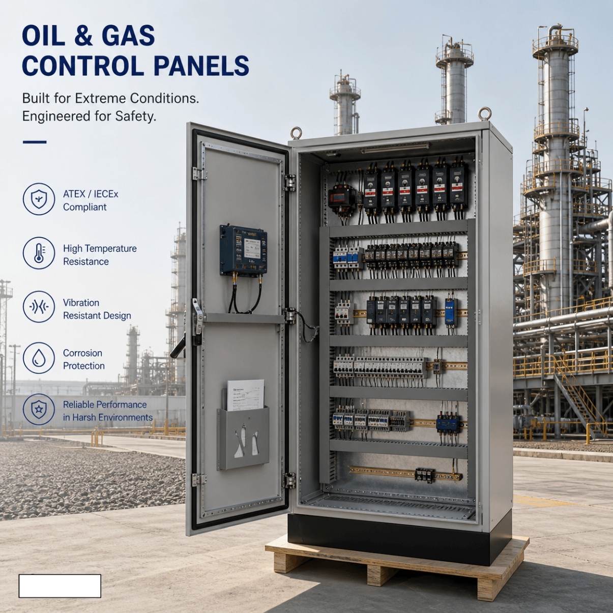
Oil & Gas Control Panels
Oil and Gas Control Panels
UniRegal supplies custom oil and gas control panels for pump skids, pipeline auxiliaries, tank farms, utility systems and remote monitoring. Each panel is configured from the installation location, instrument index, control narrative, cause-and-effect matrix, communications and documented project requirements.
Specifications
- Application
- Custom Industrial Automation
- Control Method
- PLC / Relay Based
- Voltage
- 220V / 380V / 480V Available
- Protection Rating
- IP54 / IP65 Optional
- Communication Protocol
- Modbus / Profinet / Ethernet/IP
- Testing
- FAT Before Shipment
- Customization
- Available
Product Positioning:
Project-specific control panels for oil and gas process packages, auxiliary systems and remote sites, developed from the installation location, field signals, control narrative and project requirements.
Oil & Gas Control Panels Built Around Site Conditions and Control Boundaries
An oil and gas control panel must be specified from its installation location, process function and field interfaces. Before selecting a PLC, enclosure or communication device, the project must establish whether the panel is installed in a non-hazardous or classified area and whether it performs normal process control or interfaces with safety-related systems.
UniRegal supplies project-specific control panels for:
- Pump and transfer skids
- Pipeline auxiliary systems
- Tank-farm utility equipment
- Metering-system auxiliary control
- Fuel-handling equipment
- Produced-water and injection packages
- Compressor auxiliary systems
- Remote monitoring stations
- Oil and gas utility systems
- Existing control-panel replacement
Control platforms: Relay, PLC, RTU and HMI
Field signals: Pressure, flow, level, temperature and equipment status
Communication: Project-defined SCADA and industrial protocols
Installation: Indoor, outdoor, skid-mounted or electrical-room applications
Project basis: Area information, instrument index, control narrative and interface documents
Any hazardous-location, explosion-protection, functional-safety or third-party certification requirement is treated as a separate qualification item and is included only when explicitly confirmed in writing.
Quick Answer: What Is an Oil & Gas Control Panel?
An oil and gas control panel monitors and controls process or auxiliary equipment used in oilfield, pipeline, terminal, tank-farm and process-package applications. It may collect instrument signals, operate pumps and valves, execute normal process logic, display alarms and exchange information with an RTU, SCADA or plant control system.
Its specification should answer five questions:
- Where will the panel be installed?
- What equipment and process does it control?
- Which field signals originate in classified areas?
- Does it perform normal control or interface with a safety-related system?
- Which standards, certificates and inspections does the project require?
A cabinet photo, PLC model and voltage are not enough to answer these questions.
Buyer Decision Information
Start with the Installation Location
Installation Location | Panel Direction | Information Required |
|---|---|---|
Indoor non-hazardous electrical room | Standard industrial control panel | Ambient conditions and project electrical standard |
Outdoor non-hazardous location | Weather-protected outdoor panel | Temperature, solar exposure, dust, rain and corrosion |
Skid-mounted non-hazardous location | Package control panel | Skid interfaces, vibration and cable routing |
Safe area connected to classified-area instruments | Associated field-interface design | Area documents, field-device certificates and loop data |
Hazardous classified location | Separately qualified certified solution | Zone/Class, gas group, temperature class and certification |
Offshore or coastal non-hazardous area | Corrosion-resistant project configuration | Salt exposure, material, coating and inspection requirements |
Remote unattended site | RTU or remote control panel | Power budget, telemetry and communication-loss response |
The words “oil and gas” do not automatically mean that the control panel must be explosion-protected. The requirement depends on where the panel is installed and how its field circuits connect to the classified area.
Area Classification Comes Before Enclosure Selection
The panel builder should receive the project’s approved area-classification information before selecting equipment intended for a classified location or connected to classified-area circuits.
Hazardous-Area Information to Confirm
Classification Item | Why It Is Needed |
|---|---|
Classification System | IEC Zone or North American Class/Division/Zone |
Zone or Division | Defines the frequency or duration of the explosive atmosphere |
Gas or Dust Group | Defines the applicable substance grouping |
Temperature Class | Limits permitted equipment surface temperature |
Equipment Protection Level | Required where specified by the IEC-based project |
Ambient Temperature | Must remain within certified equipment conditions |
Installation Drawing | Shows the classified-area boundary |
Certification Scheme | IECEx, ATEX, UL, CSA or project-specific requirement |
Wiring Method | Defines cable, gland, conduit and termination requirements |
Inspection Requirement | Defines documentation and initial inspection scope |
Area classification should be provided or approved by the responsible EPC, owner or qualified hazardous-area specialist. UniRegal should not infer a Zone, Division, gas group or temperature class from the application name.
IP65 or NEMA 4X Does Not Mean Explosion-Proof
Ingress protection and explosion protection answer different questions.
An IP or ordinary NEMA enclosure rating addresses environmental exposure such as dust, water, rain or corrosion. It does not confirm that the enclosure or complete panel is suitable for an explosive atmosphere.
Marking or Requirement | What It Addresses |
|---|---|
IP Rating | Ingress of solid objects and water |
Ordinary NEMA Type | Environmental conditions for non-hazardous locations |
Ex Protection Marking | Equipment protection for explosive atmospheres |
Gas or Dust Group | Applicable explosive substance group |
Temperature Class | Maximum permitted surface-temperature category |
IECEx or ATEX Documentation | Conformity under the applicable scheme |
UL Hazardous-Location Marking | North American classified-location application |
Installing ordinary components inside a stainless-steel IP65 enclosure does not create a certified hazardous-area control panel.
Safe-Area Panel with Classified-Area Field Devices
A common oil and gas architecture places the main control panel in a non-hazardous electrical room while instruments and actuators remain in classified field areas.
This arrangement may require:
- Approved intrinsic-safety barriers or galvanic isolators
- Defined intrinsically safe and non-intrinsically safe terminals
- Required separation between circuit types
- Appropriate grounding and bonding
- Field-device and barrier compatibility review
- Intrinsic-safety loop calculations or entity-parameter review
- Identified cable and terminal schedules
- Appropriate installation documentation
- Certification matching the target market
The fact that the main enclosure is installed in a safe area does not remove the need to review circuits extending into the classified area.
Intrinsic-safety devices, barriers and wiring arrangements must be selected by competent personnel according to approved loop documentation. Their inclusion is not implied by the standard oil and gas panel scope.
Normal Process Control and Safety-Related Shutdowns
Oil and gas projects may contain both a basic process control system and a safety instrumented system. Their responsibilities should remain clear.
Basic Process Control
A normal PLC or RTU control panel may:
- Monitor pressure, flow, level and temperature
- Start and stop process or utility equipment
- Operate valves according to approved logic
- Manage normal process interlocks
- Display operating alarms
- Communicate with SCADA
- Record equipment status and process values
Safety-Related Interface
A standard control panel may receive or transmit approved status and shutdown-interface signals, provided the scope is defined in the project documents.
Safety Instrumented System
A SIS performs specified safety instrumented functions and is subject to the applicable functional-safety lifecycle. Its architecture, logic solver, diagnostics, separation, verification, validation and maintenance requirements must follow the approved Safety Requirements Specification.
A normal PLC, safety relay or emergency-stop circuit should not be described as SIL-rated simply because it participates in a shutdown.
The Documents That Should Define the Panel
1. Area-Classification Drawing
Identifies the classified and non-classified locations around the installation.
2. Process and Instrumentation Diagram
Shows the process equipment, piping, valves and instruments associated with the panel.
3. Instrument Index
Defines each instrument tag, measurement range, signal type, location and classification information.
4. I/O List
Identifies the physical and communication points connected to the PLC, RTU, HMI or external system.
5. Control Narrative
Explains normal start, operation, stop, local control, remote control and recovery after interruption.
6. Cause-and-Effect Matrix
Connects each confirmed process or emergency input to the required alarm, trip, valve or equipment response.
7. Electrical Load List
Identifies motors, heaters, solenoids and auxiliary loads together with their electrical requirements.
8. Project Specification
Defines standards, component preferences, enclosure requirements, inspection stages, documentation and certification.
These documents should agree with each other before panel production begins.
Cause-and-Effect Must Define More Than “Trip”
A shutdown description should state the exact cause, action, reset method and reporting requirement.
Cause | Items to Define |
|---|---|
High or Low Pressure | Setpoint source, delay, affected equipment and reset |
High or Low Level | Pump or valve action and alarm priority |
Flow Not Proven | Permitted delay and equipment response |
Pump or Motor Fault | Standby response and remote alarm |
Valve Fails to Move | Sequence hold, alarm and manual recovery |
Fire-and-Gas Interface | Approved shutdown action and signal ownership |
Emergency Stop | Affected outputs, latching and reset location |
Loss of Instrument Signal | Alarm, fallback value, hold or shutdown |
Loss of Communication | Local operation, timeout and remote indication |
Loss of Control Power | Output state and restart behavior |
Return of Power | Automatic restart, staged restart or manual release |
The panel builder should implement the approved matrix rather than decide the process-safe state independently.
Fail-Safe Output Philosophy
A project may require certain outputs to move to a defined state after loss of power, wire break, controller fault or communication failure.
The buyer should confirm:
- Whether the output is energized or de-energized during normal operation
- Required state after control-power loss
- Required valve action after solenoid-power loss
- Whether the alarm must latch
- Where reset is permitted
- Whether restart is automatic
- How bypasses or overrides are controlled
- Which status is returned to SCADA
“Fail-safe” does not mean the same output state for every process. A valve may need to fail open, fail closed or remain in position depending on the approved process design.
Oil & Gas Applications Supported by the Core Panel Scope
Pump and Transfer Skids
Control and monitoring for transfer, circulation, produced-water or injection-package pumps according to the approved package sequence.
Pipeline Auxiliary Systems
Local control for pumps, valves, heaters, analyzers or utility equipment associated with pipeline stations and packaged systems.
Tank-Farm Utilities
Control of transfer pumps, tank-level interfaces, valve status and auxiliary alarms based on approved operating and shutdown requirements.
Metering-System Auxiliary Control
Collection of flow, pressure, temperature, valve and equipment-status signals for connection with the metering package or supervisory system.
Compressor Auxiliary Systems
Control and monitoring of approved auxiliary equipment such as cooling, lubrication or ventilation systems. Compressor protection remains subject to the compressor OEM’s confirmed scope.
Fuel-Handling Equipment
Transfer-pump, valve, level and alarm interfaces for project-defined fuel-handling packages.
Produced-Water and Injection Packages
Control of pumps, valves, tanks, pressure, flow and associated package instrumentation.
Remote Monitoring Stations
PLC or RTU panels for collecting field signals, executing approved local logic and exchanging information with the site SCADA system.
PLC, RTU, HMI and SCADA Responsibilities
System Layer | Typical Responsibility |
|---|---|
PLC | Local process and equipment logic |
RTU | Remote signal collection, local logic and telemetry |
HMI | Local status, alarms, modes and authorized commands |
SCADA | Remote supervision, trends, alarms and operator commands |
Gateway | Translation between approved communication protocols |
Network Equipment | Connection between the remote panel and plant system |
A remote panel should not depend on continuous SCADA communication unless the project explicitly requires that behavior.
The control philosophy should define:
- Which functions remain local
- What happens after communication timeout
- Whether commands are maintained or cleared
- Which data is buffered during interruption
- How the panel reconnects
- Whether time synchronization is required
- Which alarms require immediate transmission
- Who owns remote-access configuration
Remote-Site Power and Restart Strategy
Remote oil and gas installations may have limited or unstable control power. Before panel design, the buyer should identify:
- Main and control-power sources
- Available UPS or battery supply
- Required operating time after mains failure
- Maximum DC power budget
- Starting loads and inrush current
- Surge and transient requirements
- Power-source monitoring
- Low-voltage disconnect requirement
- Communication equipment power
- Heater or cooling load
- Restart sequence after power restoration
Solar, battery or UPS-supported operation should only be included after the complete power budget and required autonomy have been confirmed.
Field Instruments and Signal Interfaces
Typical signals may include:
Measurement or Device | Possible Interface |
|---|---|
Pressure | Switch or transmitter |
Flow | Analog, pulse or communication signal |
Temperature | RTD, thermocouple or transmitter |
Level | Switch, transmitter or remote status |
Motor | Run, available, fault and command |
Valve | Open/closed feedback and command |
VFD | Run, fault, speed reference and communication |
Package Equipment | Available, running, fault and permissive |
Emergency Interface | Approved hardwired status or command |
Fire-and-Gas System | Project-defined interface signals |
Remote System | Serial, Ethernet or approved telemetry |
Every signal should have a tag, range, units, normal state, source, destination and required control action.
Intrinsically Safe and Non-Intrinsically Safe Signals
Where a safe-area panel connects to intrinsically safe field circuits, the design should identify:
- Barrier or isolator model
- Channel assignment
- Field-device compatibility
- Cable parameters where required
- Earthing or isolation method
- Terminal separation
- Identification color and labels
- Power-supply arrangement
- Loop drawing reference
- Applicable certificates
Ordinary and intrinsically safe circuits should not be mixed without the required separation and documentation.
Selection of barriers and confirmation of the complete intrinsic-safety loop must be part of the explicitly approved project scope.
Environmental Engineering
Oil and gas sites may expose panels to heat, solar radiation, dust, humidity, condensation, salt, chemicals and vibration. The enclosure material is only one part of the environmental design.
Environmental Inputs
Site Condition | Design Information Required |
|---|---|
Ambient Temperature | Minimum and maximum operating temperature |
Solar Exposure | Direct sunlight and sunshade requirement |
Dust and Sand | Ingress and maintenance conditions |
Rain or Washdown | Direction and intensity of water exposure |
Humidity | Condensation and heater requirements |
Corrosive Atmosphere | Chemical or salt exposure |
Vibration | Skid or structural vibration level |
Altitude | Equipment derating where applicable |
Cable Entry | Direction, gland type and field cable schedule |
Maintenance Access | Door clearance and component replacement space |
Stainless steel is not automatically the correct answer for every corrosive environment. Material grade, surface finish, coating, hardware and external exposure should be reviewed together.
Thermal-management devices must also remain compatible with the required environmental and hazardous-location strategy.
Cable Entry, Glands and Field Terminations
Cable-entry requirements should be defined before the enclosure is manufactured.
The project should confirm:
- Top, bottom or side entry
- Gland plate material
- Cable quantity and diameter
- Armoured or unarmoured cable
- Hazardous-location gland requirement
- Spare entries
- Segregation of power, control, communication and IS circuits
- Earthing arrangement
- Shield termination method
- Field terminal quantity
- Terminal test or disconnect requirement
A certified field device can lose its intended protection if the installed gland, cable or termination method does not match the approved installation requirements.
Alarm Design for Remote Operators
Oil and gas operators need to distinguish between a condition requiring immediate shutdown and one requiring maintenance or observation.
The alarm schedule should define:
- Alarm text
- Process tag
- Trigger condition
- Delay
- Priority
- Automatic equipment response
- Acknowledgement requirement
- Reset condition
- First-out indication where required
- SCADA reporting
- Event timestamp
- Shelving or suppression authority where applicable
A single “Common Fault” output may be adequate for a simple auxiliary panel but is insufficient when remote operators need to determine whether the site has stopped, degraded or only requires maintenance.
Local and Remote Operation
Local Mode
Allows authorized field operation for testing or maintenance. The project should identify which shutdowns and equipment protections remain active.
Remote Mode
Allows the approved SCADA or control system to issue commands while the local controller executes the equipment-level sequence.
Communication Failure
The panel should enter the approved operating state rather than respond unpredictably. Depending on the application, it may continue locally, clear remote commands, hold a setpoint or stop controlled equipment.
Mode Transfer
Transfer between local and remote control should not cause an unexpected start. The active control source should be visible locally and remotely.
Retrofit and Replacement Projects
Control-panel replacement in an operating oil and gas facility requires verification of the installed system rather than reliance on old drawings alone.
Information to Collect
- Existing panel photographs
- Electrical drawings
- PLC, RTU, HMI and communication models
- Available software backups
- Field instrument list
- Current I/O list
- Area-classification drawing
- Existing equipment certificates
- Cause-and-effect matrix
- Current alarm list
- Field cable and terminal schedule
- Available shutdown duration
- Temporary operating requirements
- Modifications made after original commissioning
Retrofit Decisions
The buyer should confirm whether the project requires:
- Like-for-like replacement
- PLC or RTU migration
- Replacement of obsolete components
- Reuse of existing field cables
- Reuse of barriers or isolators
- Communication-protocol migration
- Revised alarm or control logic
- Staged installation
- Parallel operation during changeover
- Site survey and loop verification
Existing shutdown logic should not be transferred into new software until it has been reviewed against the current approved documentation.
Factory Acceptance Testing
FAT should verify the approved control narrative, I/O list and cause-and-effect matrix rather than only proving that the panel powers on.
Typical FAT Scope
- Component and BOM verification
- Enclosure, nameplate and label inspection
- Wiring, grounding and terminal checks
- Controller and communication hardware checks
- Digital I/O simulation
- Analog-signal injection and scaling
- RTD or thermocouple simulation where included
- Pump, motor and valve command simulation
- Valve-position feedback checks
- Normal sequence testing
- Cause-and-effect testing
- Emergency-interface simulation
- Alarm priority and first-out checks
- Local and remote mode checks
- Communication-loss response
- Control-power failure and restoration
- RTU or SCADA point verification
- Program and parameter backup
- Open-item recording
What FAT Can Verify
FAT can confirm panel wiring, signal scaling, sequence execution, output actions, alarm messages, local controls and panel-side communications using simulated field conditions.
What FAT Cannot Fully Verify
FAT cannot determine whether the owner’s area classification is correct, validate the complete installed hazardous-area wiring system, prove field-device performance, certify an unapproved assembly, complete SIL verification or reproduce the live process and communication network.
Those activities require the responsible engineering, certification, installation and commissioning parties.
Documentation for Approval and Handover
Depending on the confirmed scope, the documentation package may include:
- General arrangement drawing
- Electrical schematic
- Panel layout
- Bill of materials
- I/O list
- Terminal schedule
- Cable schedule
- Instrument interface list
- Network architecture
- Control narrative
- Cause-and-effect matrix
- Alarm and trip list
- Field loop diagrams where included
- Barrier or isolator schedule where included
- Software and parameter backups
- Component certificates supplied with the approved BOM
- FAT procedure and test record
- Operation and maintenance information
- Packing list
Certificates should be traceable to the actual component model supplied. A folder of unrelated certificates does not demonstrate compliance of the complete panel.
How to Compare Oil & Gas Control Panel Quotations
Quotation Item | Question to Ask |
|---|---|
Installation Location | Is the panel for a safe or classified area? |
Area Information | Has the supplier received the classification drawing? |
Certification | Is certification included, excluded or still under review? |
Field Circuits | Are any circuits connected to classified-area devices? |
IS Interfaces | Are barriers, separation and loop documentation included? |
Process Control | Is programming based on an approved narrative? |
Shutdown Interface | Is the cause-and-effect matrix included in testing? |
Functional Safety | Is the scope ordinary control, interface only or qualified SIS work? |
Environment | Are temperature, solar exposure and corrosion confirmed? |
Cable Entry | Are glands, gland plates and field cables defined? |
Remote Operation | What happens when SCADA communication fails? |
Power | Are UPS, battery and restart requirements included? |
Documentation | Which drawings, certificates and software files are supplied? |
FAT | Does testing include complete I/O and cause-and-effect simulation? |
Site Work | Who owns installation inspection, SAT and commissioning? |
The phrase “oil and gas control panel” does not prove that two quotations cover the same compliance, engineering or testing scope.
Typical Technical Configuration
All values, platforms and materials are selected according to the approved project requirements.
Item | Project-Defined Configuration |
|---|---|
Application | Pump skid, pipeline auxiliary, tank farm, utility or remote monitoring |
Installation | Indoor, outdoor, electrical room or skid-mounted |
Area Status | Non-hazardous or separately reviewed classified-area scope |
Control Architecture | Relay, PLC, RTU or PLC/RTU with HMI |
Field Signals | Dry contact, analog, pulse, RTD, thermocouple or communication |
Communication | Project-defined SCADA or industrial protocol |
Power Supply | Project-defined AC or DC supply |
Backup Power | UPS or battery when specified |
Enclosure | Project-defined material and environmental protection |
Documentation | Drawings, I/O, terminals, narrative, cause-and-effect and FAT |
Certification | Included only when explicitly confirmed |
No UL, IECEx, ATEX, hazardous-location or SIL claim should be assumed unless the exact assembly scope and certification route are stated in the quotation.
Information Required for Quotation
Site and Installation
- Project and site type
- Panel installation location
- Indoor, outdoor or skid-mounted arrangement
- Area-classification drawing
- Zone, Class/Division, group and temperature class where applicable
- Ambient temperature
- Dust, rain, humidity and corrosion conditions
- Certification and inspection requirements
Process and Equipment
- P&ID
- Equipment list
- Motor and load schedule
- Valve list
- Instrument index
- Normal operating sequence
- Cause-and-effect matrix
- Required local and remote modes
Signals and Automation
- I/O list
- Signal types and ranges
- PLC or RTU platform
- HMI requirements
- SCADA point list
- Communication protocol
- Network architecture
- Software handover requirements
Electrical and Mechanical
- Incoming and control power
- UPS or battery requirements
- Cable-entry direction
- Cable schedule
- Gland requirements
- Enclosure material
- Mounting arrangement
- Spare I/O and terminals
Project Deliverables
- Required drawings
- FAT procedure
- Documentation format
- Certification scope
- Inspection hold points
- Site commissioning responsibility
- Delivery schedule
Frequently Asked Questions
Is an IP65 or NEMA 4X control panel suitable for a hazardous area?
Not automatically. These ratings primarily address environmental protection. Hazardous-area suitability depends on the area classification, protection method, equipment marking, wiring system, ambient conditions and applicable certification. These requirements must be reviewed separately.
Who should provide the hazardous-area classification?
The classification should be prepared or approved by the owner, EPC, qualified hazardous-area specialist or another responsible engineering party. The panel builder should use the approved classification rather than infer the Zone or Division from the equipment application.
Can a normal control panel be installed in a safe area and connect to instruments in a hazardous area?
Yes, this architecture is common, but the field circuits may require approved barriers, isolators, separation, grounding and loop documentation. The complete circuit must be reviewed according to the project classification and certification scheme.
Does using certified components make the complete panel certified?
No. Component certification does not automatically certify the complete assembly. Component use, enclosure, wiring, terminals, glands, ambient rating, markings, documentation and manufacturing route must all comply with the applicable assembly or installation requirements.
Is a normal PLC panel the same as an ESD or SIS panel?
No. A normal PLC panel performs basic process control. A SIS implements specified safety instrumented functions under a functional-safety lifecycle. The safety requirements, architecture, SIL verification, validation and maintenance scope must be separately defined.
Can UniRegal supply an explosion-proof or IECEx/ATEX panel?
Such requirements must be reviewed separately against the exact area classification, protection method, target market, certification route and manufacturing capability. They should not be assumed from the Oil & Gas Control Panels product name or an IP-rated enclosure.
How should loss of SCADA communication be handled?
The project should define whether the local panel continues operating, clears remote commands, uses fallback setpoints or stops equipment. Essential local interlocks should not depend on an undefined communication connection.
What should be included in a cause-and-effect matrix?
It should identify every confirmed initiating condition, affected output, equipment action, valve position, alarm, delay, latch, reset method and SCADA indication. It should also distinguish normal process interlocks from safety-related shutdown functions.
Can FAT prove that the panel meets the site hazardous-area requirements?
FAT can verify the panel against approved drawings and simulate control functions. It cannot validate the owner’s area classification or the complete field installation. Hazardous-area compliance also depends on certification, installation, glands, cables, grounding, inspection and documentation.
What enclosure material should be used offshore or near the coast?
The decision depends on salt exposure, chemicals, temperature, maintenance and project coating specifications. Stainless steel may be appropriate, but its grade, finish, hardware and surrounding materials must be confirmed rather than selected from the word “offshore” alone.
Can an old oil and gas control panel be replaced without changing field wiring?
Possibly, but every field circuit, voltage, signal type, terminal, classification and device certificate must first be verified. Reusing cables or barriers should not be assumed from the existing terminal numbers.
What information is required for an accurate quotation?
Please send the installation location, area-classification information, P&ID, instrument index, I/O list, control narrative, cause-and-effect matrix, communication requirements, power supply, environmental conditions and required certification documents.
Request an Oil & Gas Control Panel Quotation
Send UniRegal your area information, P&ID, equipment list, instrument index, I/O list, control narrative, cause-and-effect matrix and SCADA requirements.
We first review the installation location, control boundary, field circuits, environmental conditions and documentation requirements. The quotation then states what is included, what requires third-party review and what remains the responsibility of the EPC, owner or site contractor.
We confirm receipt within 24 hours and advise the next technical step within 1–2 business days, depending on project complexity.
Related Indutriail Page: