
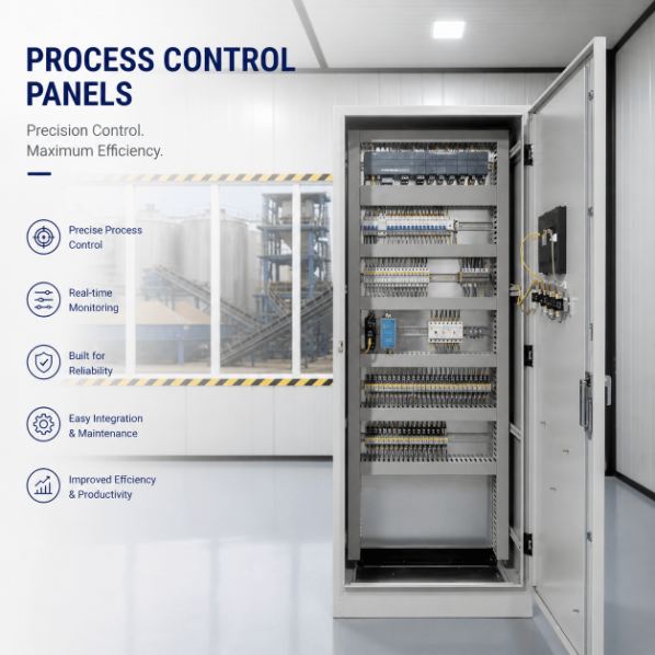
Process Control Panels
Process Control Panel Supplier
Process control panels for continuous, batch and hybrid lines — with enclosures, PLC and instrumentation integrated by Foshan suppliers.
Specifications
- Application
- Custom Industrial Automation
- Control Method
- PLC / Relay Based
- Voltage
- 220V / 380V / 480V Available
- Protection Rating
- IP54 / IP65 Optional
- Communication Protocol
- Modbus / Profinet / Ethernet/IP
- Testing
- FAT Before Shipment
- Customization
- Available
Quick Answer
Process control panels run closed-loop control - temperature, pressure, flow, level - with analog I/O, PID loops and sequencing. UniRegal builds to your P&ID using multi-brand PLC/HMI, UL 508A available, ~15-day lead time. Provide your process variables and I/O list for a build-to-print quotation.
Process Control Panels for Stable, Measurable Industrial Processes
UniRegal supplies custom process control panels for industrial systems that must measure and regulate temperature, pressure, flow, level, pH, conductivity, speed, or other process conditions.
Each panel is developed around the relationship between field instruments, control logic, operator decisions, and final control elements such as control valves, VFD-driven pumps, heaters, mixers, and dosing equipment.
A process control panel should do more than power equipment and display values. It should help operators understand the current process condition, identify what is preventing operation, adjust approved setpoints, respond to abnormal conditions, and recover the process without introducing new instability.
Buyer Decision Information: Is This the Right Panel?
Project Requirement | Recommended Product Direction |
Temperature, pressure, flow, level, pH, or conductivity must be maintained using feedback control | Process Control Panel |
The system combines PID loops, instruments, valves, drives, alarms, trends, and operator setpoints | Process Control Panel |
A batch process requires recipes, timed steps, permissives, and process-variable control | Process Control Panel |
The requirement mainly concerns PLC hardware, I/O capacity, HMI, and communication | PLC Control Panel |
The requirement mainly concerns duty/standby pumps, level switches, and pressure control | Pump Control Panel |
The system is specifically for filtration, RO, dosing, backwash, and treatment sequences | Water Treatment Control Panel |
The project controls the complete mechanical cycle of an OEM machine | Machinery Control Panel |
The project contains only several independent temperature loops | A standalone temperature or heat control solution may be sufficient |
A process control panel is normally justified when several measurements and equipment responses must work together as one process rather than as independent electrical loads.
Process Control Panel Capability Overview
Parameter | Available Project Options |
Process Type | Continuous, Batch, or Hybrid |
Project Route | Build-to-Print or Design-and-Build |
Control Architecture | PLC, HMI, Standalone PID, Remote I/O, SCADA Interface, or Hybrid |
Process Inputs | 4–20 mA, 0–10 V, RTD, Thermocouple, Pulse, Frequency, or Dry Contact |
Controlled Equipment | Control Valves, Pumps, VFDs, Heaters, Mixers, Dosing Equipment, and Actuators |
Control Functions | PID, On/Off, Ratio, Cascade, Sequence, Duty/Standby, or Project-Specific Logic |
Operator Interface | Local Controls, HMI, Remote HMI, or SCADA |
Communication | Hardwired I/O or Project-Specified Industrial Protocols |
Enclosure | Wall-Mounted or Floor-Standing |
Enclosure Material | Carbon Steel or Stainless Steel |
Environment | Indoor, Outdoor, Wet, Dusty, Washdown, Hot, or Corrosive Conditions |
Testing | Electrical FAT, I/O Simulation, Loop Simulation, Logic Test, and Communication Test |
Documentation | Schematics, I/O List, Instrument List, Loop Information, Alarm List, and FAT Records |
Production Scope | Prototype, Project Batch, Repeat Build, or Retrofit |
All functions, environmental ratings, standards, test procedures, and documentation requirements must be confirmed for the individual project.
A Process Control Panel Begins With the Process Basis
A process control system cannot be defined from cabinet dimensions or an equipment list alone.
The engineering basis should explain what the process is expected to achieve and which variables must remain within defined operating limits. It should also identify the consequences of a measurement failure, equipment fault, utility interruption, or operator action.
Before panel design begins, the project should define:
- Normal operating ranges
- Minimum and maximum allowable setpoints
- Instrument measurement ranges
- Required control accuracy or acceptable variation
- Startup and shutdown conditions
- Manual and automatic operating authority
- Equipment permissives
- Process interlocks
- Alarm priorities and operator responses
- Final control element failure positions
- Communication-loss behavior
- Power-loss and restart behavior
- Data retention and trending requirements
- Process and safety-system boundaries
Without this information, a panel can be electrically complete while the control strategy remains unresolved.
What a Complete Process Control Loop Requires
A control loop is only as effective as its weakest element.
Loop Element | Required Project Information |
Process Variable | What must be controlled and why |
Measuring Element | Sensor or analyzer type and installation condition |
Transmitter | Output signal, range, units, accuracy, and failure behavior |
Signal Interface | PLC input type, isolation, shielding, grounding, and scaling |
Controller | Setpoint, control mode, tuning method, and operating limits |
Final Control Element | Valve, VFD, heater, damper, pump, or dosing equipment |
Feedback | Position, speed, run status, flow, pressure, or other confirmation |
Alarm Response | Warning, operator action, automatic interlock, or trip |
HMI Display | Value, units, setpoint, output, mode, alarm, and trend |
FAT Method | How the input and output will be simulated before shipment |
Commissioning Method | How the complete installed loop will be checked and tuned |
Installing a PLC with a PID function does not automatically create a stable process loop. The instrument, signal range, control valve or drive, process dynamics, and final tuning all influence performance.
Common Process Variables and Control Methods
Process Variable | Typical Measurement | Possible Final Control Element |
Temperature | RTD, Thermocouple, or Temperature Transmitter | Heater, SSR, Contactor, Control Valve, Cooling Valve, or VFD |
Pressure | Pressure Transmitter or Pressure Switch | Control Valve, VFD Pump, Compressor, or Bypass Valve |
Flow | Flow Transmitter, Pulse Meter, or Flow Switch | Control Valve, VFD Pump, or Dosing Pump |
Level | Level Transmitter, Float Switch, or Level Switch | Pump, Inlet Valve, Outlet Valve, or VFD |
pH | pH Analyzer or Transmitter | Acid or Alkali Dosing Equipment |
Conductivity | Conductivity Analyzer or Transmitter | Dosing Equipment, Diversion Valve, or Drain Valve |
Speed | Encoder, Tachometer, or Drive Feedback | VFD or Motor Controller |
Weight | Load Cell and Weight Transmitter | Feeder, Valve, Conveyor, or Dosing Equipment |
The final measurement and control method must be selected from the real process conditions. The table describes common arrangements but does not replace process or instrument engineering.
Continuous, Batch, or Hybrid Process Control?
The control architecture should match how the process operates.
Continuous Process Control
A continuous process operates for an extended period while variables such as pressure, flow, temperature, or level are regulated around approved targets.
The control panel should consider disturbances, equipment transitions, controller modes, process trends, alarm behavior, and what happens when an instrument or final control element becomes unavailable.
Batch Process Control
A batch process moves through defined production steps. Each step may require a combination of timing, equipment status, permissives, material quantities, and process-variable conditions.
The project should define recipe ownership, permitted parameter ranges, step transitions, hold and resume behavior, abort conditions, incomplete-batch recovery, batch records, and operator authority.
An ISA-88-based structure can be considered when the customer requires standardized batch models, recipes, equipment phases, or repeatable implementation across several systems.
Hybrid Process Control
Many projects combine both approaches. A tank may follow a batch filling and mixing sequence while temperature, pressure, or pH is regulated continuously during individual steps.
In these projects, the sequence logic and feedback loops must be coordinated so that a batch step cannot advance merely because a timer has expired when the required process condition has not been achieved.
A P&ID Is Essential, but It Is Not the Complete Control Strategy
A piping and instrumentation diagram identifies equipment, instruments, control functions, and their relationships. It provides an important foundation for process control engineering and instrument identification.
However, a P&ID may not explain:
- How the process starts
- Which permissives must be satisfied
- Which setpoint has control authority
- What happens after an instrument fault
- Whether an alarm stops equipment
- How manual mode is restricted
- How a batch step advances
- What happens after a communication failure
- How the process recovers after power loss
- Which functions belong to the basic control system or safety system
For an accurate quotation, the P&ID should be supported by a control narrative, instrument list, I/O list, alarm and interlock requirements, equipment data, and defined responsibility boundaries.
Information Required for an Accurate Quotation
Information | Why It Matters |
Process Description | Explains the intended operating result |
PFD or P&ID | Identifies equipment, instruments, and process relationships |
Control Narrative | Defines automatic operation, modes, and equipment responses |
Instrument List | Identifies tags, ranges, units, signals, and device models |
I/O List | Defines required digital and analog channels |
Motor and Load List | Defines protection, switching, VFD, and power requirements |
Control Valve Information | Defines signal, actuator, fail position, and feedback |
Alarm List | Defines conditions, priorities, delays, and operator responses |
Cause-and-Effect Matrix | Defines automatic actions caused by abnormal conditions |
Batch or Recipe Requirements | Defines steps, parameters, hold points, and records |
HMI Requirements | Defines screens, trends, setpoints, user access, and languages |
SCADA or DCS Interface | Defines tags, protocol, data ownership, and control authority |
Supply Voltage | Determines electrical component ratings |
Installation Environment | Determines enclosure, sealing, cooling, and material |
Hazardous-Area Information | Determines whether barriers or special interfaces are required |
Applicable Standards | Defines design, testing, marking, and documentation scope |
FAT and SAT Requirements | Defines what must be demonstrated and where |
Destination Country | Helps establish electrical and documentation requirements |
If the full package is not available, send the P&ID, process description, instrument list, equipment list, and intended control method first. The missing information can then be identified before the quotation is finalized.
Instrument Signals and Analog Input Engineering
Analog signal details must be confirmed before hardware selection and programming.
4–20 mA Signals
A 4–20 mA loop should define whether the transmitter is loop-powered or separately powered, the measuring range, engineering units, fault indication, cable arrangement, isolation requirement, and grounding method.
The PLC program must scale the actual configured transmitter range. Assuming that every pressure or flow transmitter uses the same range can produce incorrect displays, alarms, and control responses.
0–10 V Signals
Voltage signals may require additional attention to cable length, common references, grounding, and electrical noise. The source and receiving-device specifications should be reviewed together.
RTD and Thermocouple Inputs
The sensor type, wiring method, temperature range, extension cable, cold-junction requirements, and input-module compatibility should be confirmed. An RTD or thermocouple should not be treated as a general analog signal.
pH, Conductivity, and Other Analyzers
Analytical sensors are normally connected through a suitable analyzer or transmitter. The project should identify the analyzer output, range, calibration responsibility, temperature compensation, maintenance condition, and response to an invalid reading.
Pulse and Frequency Inputs
Flowmeters, encoders, and speed sensors may require high-speed inputs or dedicated modules. Pulse value, frequency range, electrical type, and totalization requirements must be stated.
Signal Isolation, Shielding, and Grounding
Signal quality cannot be judged only from the PLC input specification.
The design review should consider:
- Instrument power-source arrangement
- Ground potential differences
- Shield termination
- Separation between power and signal wiring
- Analog signal isolation
- Surge exposure
- VFD-related electrical noise
- Cable length and route
- Intrinsically safe circuit requirements
- Communication cable grounding
- Field junction boxes and marshalling
The correct arrangement depends on the instrument, field wiring, site grounding system, and applicable project standards. A signal isolator should be installed because it solves an identified interface problem, not simply because the loop is analog.
Selecting the Control Architecture
PLC-Based Process Control
A PLC-based panel may be suitable when the project combines process loops with equipment sequencing, motor control, valves, interlocks, local HMI operation, and packaged-equipment integration.
The quotation should state whether PID function blocks, sequence programming, alarms, trends, communications, and source-code delivery are included.
Standalone PID Control
Standalone PID controllers may suit a limited number of independent loops where local indication and adjustment are required without a larger automation system.
The buyer should still confirm setpoint limits, alarm outputs, communication, heater or valve control, and how each controller interacts with the rest of the process.
SCADA or DCS Integration
A local process control panel can exchange measurements, alarms, commands, and status with a plant SCADA or DCS.
The interface document should define:
- Tag list
- Data type
- Engineering units
- Read and write authority
- Setpoint ownership
- Local and remote modes
- Communication-failure response
- Alarm ownership
- Time synchronization
- Historical data responsibility
- Network and cybersecurity responsibilities
“SCADA ready” is not a complete integration specification. The protocol and tag list must be supported by an agreed control-authority model.
Control Valves, VFDs, Heaters, and Other Final Elements
A process cannot be controlled more accurately than the final control element allows.
Control Valves
The process engineer or valve specialist should confirm valve sizing, process conditions, material, actuator, positioner, signal, travel, fail position, and feedback requirements.
An oversized, undersized, slow, sticking, or incorrectly selected valve may prevent stable control even when the PLC program and PID tuning are correct.
VFD-Controlled Pumps and Fans
The project should establish the controlled variable, minimum and maximum permitted speed, acceleration requirements, motor data, local and remote authority, drive-fault response, bypass requirement, and feedback signals.
Electric Heaters
Heater control may use contactors, SSRs, thyristor controllers, or other approved switching devices. Heating load, switching frequency, thermal response, overtemperature protection, and cooling requirements must be reviewed.
Where a separate high-limit function is required, it should be defined independently from the normal temperature-control loop.
Dosing Equipment
Dosing control should establish chemical concentration, required dosing range, flow-paced or feedback control, pump capacity, calibration method, low-level response, permissives, and maximum output limits.
The panel should not be expected to correct an incorrectly sized pump or unsuitable chemical-injection arrangement through software alone.
Alarm, Interlock, and Trip Are Not the Same
Function | Primary Purpose | Typical Response |
Status | Informs the operator about current equipment or process condition | Display only |
Alarm | Requires operator awareness or action | Message, indication, and acknowledgement |
Permissive | Prevents an operation from starting until conditions are satisfied | Start command blocked |
Interlock | Automatically changes or stops an operation when a defined condition occurs | Programmed control action |
Trip | Moves equipment or the process toward a defined protected state | Immediate automatic action |
Safety Instrumented Function | Performs an approved safety function through a defined SIS architecture | Action defined by the safety requirements specification |
The alarm list should specify priority, setpoint, units, delay, deadband, acknowledgement behavior, and required operator response where applicable.
Every abnormal signal does not need to become an alarm. Excessive or poorly prioritized alarms can make it harder for operators to identify the condition that genuinely needs attention.
Basic Process Control System and SIS Boundaries
A standard process control panel should not automatically be treated as a safety instrumented system.
If the project requires safety instrumented functions, the buyer or responsible safety authority should provide an approved safety requirements specification that defines the function, required SIL, sensors, logic solver, final elements, independence requirements, testing, and validation responsibilities.
IEC 61511 applies specific lifecycle requirements to safety instrumented systems in the process industry. These requirements should not be claimed merely because a safety PLC, relay, or emergency-stop circuit has been added to a general process control panel.
The quotation should state clearly whether the project includes:
- Basic process control only
- Process interlocks
- Equipment protection
- Safety-related interfaces
- An independently specified SIS
- Integration with an existing SIS
HMI Design for Process Operators
A process HMI should make abnormal conditions easier to recognize while still supporting normal operation.
Depending on project scope, the interface may include:
- Process overview
- Equipment-detail screens
- Control-loop faceplates
- Process value, setpoint, and controller output
- Manual, automatic, and cascade modes
- Alarm summary and history
- Process trends
- Permissive and interlock status
- Instrument communication quality
- Valve and actuator status
- Batch-step status
- Recipe parameters
- User access levels
- Maintenance and calibration information
The HMI should display consistent instrument tags and engineering units. Setpoint limits, manual output authority, alarm acknowledgement, recipe editing, and maintenance access should be controlled according to the approved operating philosophy.
Process Trends and Data Requirements
Trend data can help operators determine whether the process is stable, whether a controller is oscillating, and what occurred before an alarm or shutdown.
Before implementation, confirm:
- Which process values must be recorded
- Required sample or storage interval
- Required retention period
- Whether data is stored in the HMI, PLC, SCADA, historian, or another system
- Whether batch records are required
- Required time synchronization
- Export format
- User access and data ownership
- Responsibility for database and server maintenance
A local HMI trend is not automatically equivalent to a plant historian or validated production record.
Factory Acceptance Testing
The FAT should test the agreed control-system scope rather than only confirm that the panel powers on.
Electrical and Hardware FAT
Testing may include:
- Component and model verification
- Panel layout inspection
- Wire and terminal verification
- Protective bonding and grounding inspection
- Control-voltage verification
- Power-on testing
- Label and nameplate review
- Drawing consistency check
I/O and Loop Simulation
Testing may include:
- Digital input and output simulation
- 4–20 mA input simulation
- Analog output measurement
- RTD or thermocouple input simulation
- Pulse-input simulation
- Range and engineering-unit verification
- Alarm setpoint and delay verification
- Instrument-failure response
- Control-loop response to simulated process values
- Valve or VFD command-output verification
Software and Operator FAT
Testing may include:
- Automatic and manual modes
- Startup and shutdown logic
- Permissives and interlocks
- Alarm messages and priorities
- HMI screens and navigation
- Setpoint and output limits
- Batch-step transitions
- Communication with simulated external systems
- Power-loss and restart response
- Program and parameter backup
What a Panel FAT Can and Cannot Prove
FAT Can Verify | FAT Cannot Fully Prove Without the Process |
Correct PLC and HMI configuration | Final PID tuning |
Correct I/O assignment and scaling | Process stability under real production conditions |
Response to simulated instrument signals | Instrument accuracy after field installation |
Alarm and interlock logic | Control-valve performance under actual flow and pressure |
Communication mapping | Final network performance at the customer’s plant |
Command output to valves, VFDs, and heaters | Mechanical response of installed equipment |
Batch or sequence logic under simulated conditions | Product quality, throughput, or utility consumption |
Documentation consistency | Complete installed-loop performance |
A successful FAT reduces avoidable commissioning problems, but it does not replace loop checks, calibration, tuning, and process-performance testing at the final site.
Site Commissioning and Loop Tuning
Final commissioning may require cooperation between the panel supplier, process designer, instrument supplier, equipment supplier, system integrator, and end user.
Site work may include:
- Field-wire verification
- Instrument calibration confirmation
- Loop checks from instrument to HMI
- Analog range and unit verification
- Control-valve direction and fail-position checks
- VFD rotation and speed-limit checks
- Heater output and high-limit checks
- Communication verification
- Alarm and interlock testing
- Process startup support
- PID loop tuning
- Batch or recipe verification
- Operator training
- SAT documentation
PID tuning normally requires the actual installed process because tank volume, piping, valve response, heat transfer, product properties, utility conditions, and process delay affect controller behavior.
The quotation should specify who is responsible for initial controller parameters, final tuning, process-performance acceptance, and return visits.
Responsibility Matrix
Project Party | Typical Responsibility |
Process Owner or EPC | Process basis, operating ranges, P&ID, control philosophy, acceptance requirements |
Process Engineer | Process calculations, operating limits, control strategy, and equipment requirements |
Instrument Engineer or Supplier | Instrument type, range, accuracy, installation, and calibration information |
Valve or Equipment Supplier | Equipment sizing, material, actuator selection, performance, and failure behavior |
Safety Authority | Safety assessment, SRS, SIL requirements, and validation plan |
Panel Supplier | Electrical design, approved hardware integration, wiring, PLC/HMI scope, and panel FAT |
System Integrator | Plant-system integration, network interfaces, SCADA/DCS configuration, and coordinated testing |
Commissioning Team | Installed loop checks, equipment response, process tuning, SAT, and handover |
Actual responsibilities must be defined contractually. The matrix prevents important tasks from being assumed by several parties or omitted entirely.
Documentation Package
Depending on the agreed supply scope, available documents may include:
- General arrangement drawing
- Single-line diagram
- Electrical schematics
- Panel layout
- Bill of materials
- I/O list
- Instrument list
- Terminal plan
- Field-connection schedule
- Loop information or loop drawings
- Control narrative
- Alarm and interlock list
- Cause-and-effect matrix
- PLC hardware configuration
- Communication tag list
- HMI screen list
- Software and parameter backups
- FAT procedure
- FAT report
- As-built drawings
- Component datasheets
- Packing list
Required document formats, drawing conventions, instrument-tag rules, software versions, languages, source files, passwords, and revision procedures should be confirmed before ordering.
Retrofit Projects
A retrofit should begin by documenting how the existing process operates, not only by recording the installed PLC model.
The review may require:
- Existing P&ID
- Electrical drawings
- Panel photographs
- PLC and HMI backups
- Instrument list and configured ranges
- Control-valve and actuator information
- VFD parameters
- Alarm and interlock list
- Operator descriptions of normal operation
- Known process-control problems
- Historical trends where available
- Required shutdown period
- Field-wiring survey
- Cutover and rollback plan
Existing instruments should not be reused only because they still produce a signal. Range, accuracy, calibration condition, material compatibility, electrical interface, documentation, and spare-part availability should be checked.
The retrofit scope should also state whether the original control strategy will be reproduced, corrected, or redesigned.
Typical Applications
Process control panels may be used for:
- Continuous process skids
- Batch mixing systems
- Tank filling and transfer systems
- Process heating and cooling
- Chemical dosing systems
- Industrial mixing equipment
- Food and beverage processes
- Water and fluid-management systems
- Pressure and flow-control systems
- OEM process equipment
- Existing process-system retrofits
Industry-specific requirements should be confirmed separately. A food, pharmaceutical, chemical, water, or hazardous-area project may require different materials, documentation, validation, or safety provisions.
What Affects Price and Lead Time?
Process control panel cost depends on the engineering and validation scope as well as the physical cabinet.
Important commercial factors include:
- Number of digital and analog I/O points
- Instrument signal types
- Number and complexity of control loops
- PLC, HMI, and communication architecture
- Batch or recipe requirements
- Alarm and interlock complexity
- SCADA or DCS integration
- Number of VFDs, heaters, valves, and controlled loads
- Signal isolation and hazardous-area interfaces
- Enclosure material and environmental protection
- Software development
- Documentation requirements
- FAT simulation method
- Witness testing
- Site commissioning and PID tuning
- Completeness of the process documents
- Component availability
- Certification or inspection requirements
An inexpensive panel can create a more expensive project if instrument ranges, alarm behavior, control authority, software ownership, or commissioning responsibilities have not been included.
How to Compare Process Control Panel Quotations
Scope Item | Question the Buyer Should Ask |
Process Review | Are the P&ID, process description, and control narrative reviewed? |
Instrument Integration | Are signal types, ranges, units, isolation, and field power included? |
Control Loops | Are PID configuration and initial parameters included? |
Final Tuning | Is site tuning included or excluded? |
Alarm Management | Are priorities, delays, deadbands, and operator responses defined? |
HMI | Which screens, trends, setpoints, and user levels are included? |
SCADA/DCS | Who supplies the tag list and completes integration testing? |
Batch Control | Are recipes, reports, hold, resume, and abort functions included? |
Safety Scope | Is this basic process control or an approved SIS scope? |
FAT | Which signals, loops, alarms, and interfaces will be simulated? |
Documentation | Are as-built drawings, source files, and test records included? |
Software Ownership | Will editable PLC and HMI source files and passwords be delivered? |
Commissioning | Who performs loop checks, startup, tuning, and SAT? |
Retrofit Cutover | Who verifies existing wiring and manages the changeover? |
The quotation should describe these responsibilities clearly enough that the buyer can identify what remains outside the panel supplier’s scope.
Frequently Asked Questions
What is the difference between a process control panel and a PLC control panel?
A PLC control panel is defined mainly by its automation hardware, I/O, software, HMI, and communication architecture. A process control panel is defined by the process measurements, control loops, instruments, final control elements, alarm philosophy, operating ranges, trends, and commissioning requirements it must support.
Is a P&ID enough to quote a process control panel?
A P&ID provides an important starting point, but it rarely defines the complete control scope. An accurate quotation may also require an instrument list, I/O list, control narrative, alarm and interlock list, equipment data, HMI requirements, communication details, and FAT responsibilities.
Who should define the instrument ranges and engineering units?
The process or instrument engineer should approve the measurement range, engineering units, accuracy, alarm limits, and instrument-failure behavior. The panel supplier can configure and test the corresponding PLC scaling after those values have been confirmed.
Can PID loops be fully tuned before the panel is shipped?
The controller configuration and basic response can be tested using simulated signals. Final tuning normally requires the installed process because process volume, delay, heat transfer, piping, valve response, product characteristics, and operating conditions affect loop behavior.
Should we use a PLC PID function or standalone PID controllers?
A PLC may be more suitable when several loops interact with sequences, equipment, alarms, HMI screens, and plant communications. Standalone controllers may suit a small number of independent loops. The decision should also consider maintenance skills, spares, operator access, and future expansion.
What should a process-loop FAT include?
A loop FAT may verify the simulated input signal, configured range, engineering units, HMI indication, alarm thresholds, controller mode, setpoint limits, output response, failure behavior, and documentation. The exact test method should be agreed before production.
Can the panel communicate with our existing SCADA or DCS?
Yes, when the protocol, tag list, data types, control authority, setpoint ownership, alarm ownership, time synchronization, network responsibilities, and communication-loss behavior have been defined and approved.
What is the difference between an alarm, interlock, and trip?
An alarm informs the operator that attention or action is required. An interlock automatically prevents or changes an operation according to defined logic. A trip automatically moves equipment or the process toward a defined protected condition.
Does a process control panel include a safety instrumented system?
Not automatically. A safety instrumented system requires an approved safety requirements specification, defined safety functions, SIL requirements, independence, lifecycle controls, testing, and validation. These requirements must be separately identified in the project scope.
Can existing field instruments be reused during a retrofit?
They may be reused after their signal, range, calibration, condition, material compatibility, power supply, electrical interface, documentation, and spare-part availability have been checked. Producing a usable signal alone does not confirm suitability.
Can the panel manage batch recipes?
Recipe and batch functions can be included when the required parameters, limits, access levels, step logic, hold and resume behavior, abort conditions, data records, and recipe ownership have been defined before programming.
How do you prevent electrical noise from affecting analog signals?
The solution depends on the field design and may involve cable separation, shielding, grounding, signal isolation, suitable power supplies, proper instrument wiring, and review of VFD and communication cable routes. One standard solution should not be assumed for every site.
Can a factory test prove that the process will remain stable?
A FAT can verify signal scaling, control logic, alarms, HMI functions, outputs, and simulated loop response. It cannot fully reproduce actual fluid behavior, thermal delay, valve performance, instrument installation, product properties, or utility variations.
Who owns the PLC and HMI source files?
Ownership and delivery should be stated in the quotation. The project should identify whether editable source files, passwords, software versions, licenses, drive parameters, communication configurations, and backups are included in the final handover.
What causes process control panel projects to require expensive site changes?
Common causes include incorrect instrument ranges, incomplete P&IDs, undefined control authority, unsuitable control valves, missing alarm logic, overlooked signal isolation, incomplete SCADA tag lists, and FAT procedures that do not represent the final control scope.
Request a Process Control Panel Quotation
For technical review, send:
- Process description
- PFD or P&ID
- Control narrative
- Instrument and I/O lists
- Motor and load list
- Control-valve information
- Alarm and interlock requirements
- Batch or recipe requirements
- PLC, HMI, SCADA, or DCS preferences
- Supply voltage
- Installation environment
- Applicable standards
- FAT and commissioning scope
- Destination country
- Quantity and required delivery schedule
UniRegal will review the electrical, instrumentation, automation, interface, documentation, and testing requirements before defining the panel scope.