
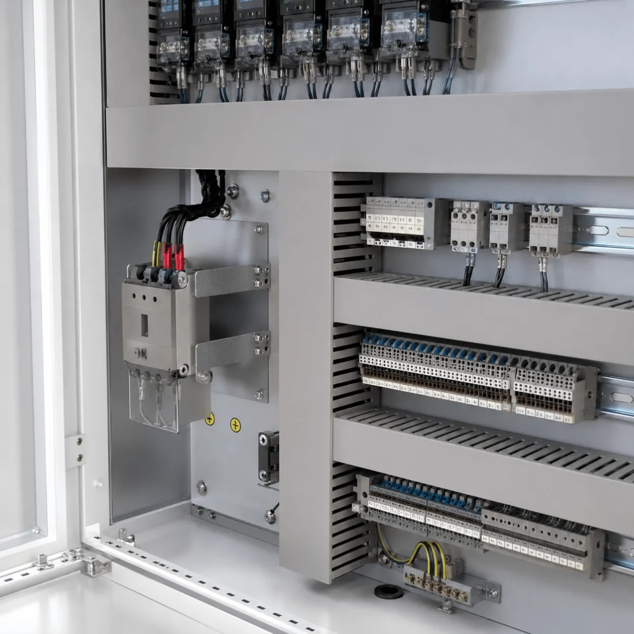
MCC Panels
PCC Panel Manufacturer & Supplier
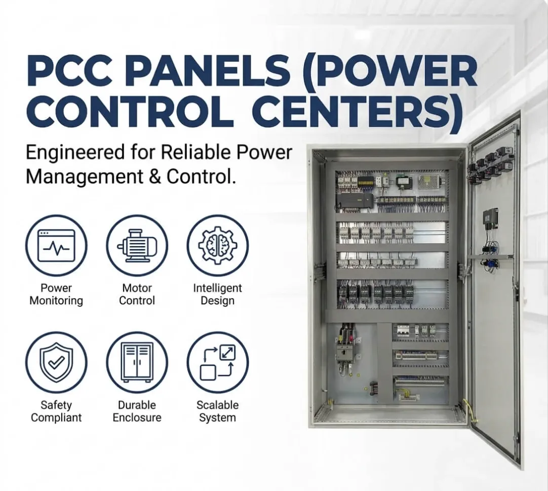
UniRegal supplies custom PCC panels for low-voltage power distribution in industrial plants. Share your SLD, incomer arrangement, feeder schedule, busbar rating, protection study and IEC 61439 requirements for quotation.
PCC Panel (Power Control Centre) for Industrial LV Power Distribution
UniRegal supplies custom PCC panels for industrial plants, utility systems, infrastructure projects, packaged electrical systems, and facilities that require centralized low-voltage power distribution.
A PCC panel normally receives power from a transformer, generator, utility source, or upstream switchgear and distributes it through main busbars to MCC panels, distribution boards, large equipment feeders, and other downstream electrical systems.
Unlike an equipment-level power control panel, the PCC is positioned near the main low-voltage source and handles the distribution architecture of a larger electrical system. Its design must therefore begin with the single-line diagram, source data, available fault current, protection philosophy, busbar arrangement, feeder schedule, cable or busduct interface, operating environment, and required verification.
Quick Answer
PCC panel stands for Power Control Centre panel or Power Control Center panel, depending on regional spelling.
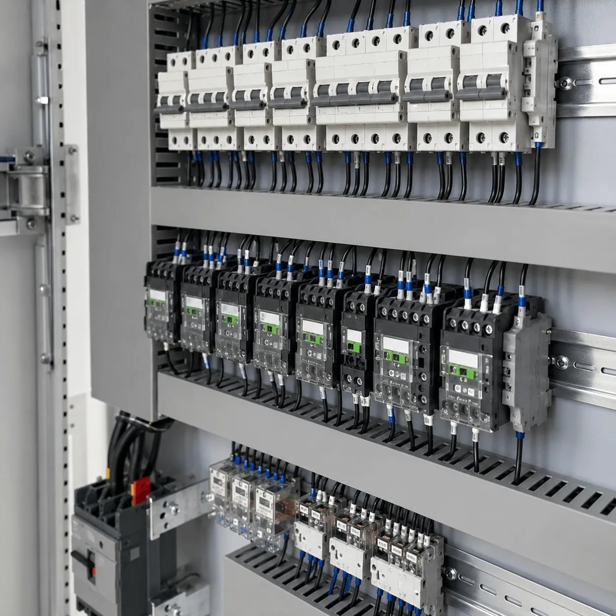
It is a central low-voltage power distribution assembly that may contain main ACB or MCCB incomers, busbars, bus couplers, outgoing feeder breakers, protection relays, metering, control power, indication, and communication devices.
For buyers, the critical question is not how many breakers can fit inside the enclosure. It is whether the entire assembly can receive, withstand, isolate, protect, and distribute the required power under the actual source, load, fault, environmental, maintenance, and operating conditions.
Where Does a PCC Panel Sit in the Electrical System?
A typical industrial distribution route may follow this structure:
System Position | Typical Function |
|---|---|
Utility, Transformer, or Generator | Supplies the electrical source |
PCC Panel | Receives the main LV supply and distributes high-capacity feeders |
MCC Panel | Controls and protects multiple motors |
Distribution Board | Supplies smaller downstream circuits |
Power Control Panel | Provides controlled power to an equipment group |
PLC or Process Control Panel | Executes automation and process logic |
Final Equipment | Motors, pumps, machines, HVAC, process equipment, and auxiliary loads |
The actual topology may differ, but the PCC usually operates closer to the main source than an MCC or equipment-level control panel.
Buyer Decision Information: Do You Need a PCC Panel?
Buyer Situation | Recommended Direction |
|---|---|
Transformer secondary power must be distributed to several plant sections | PCC Panel |
Two incomers need a controlled bus-coupler arrangement | PCC Panel |
Large feeders must supply MCCs, distribution boards, or major equipment | PCC Panel |
Main ACBs, high-current busbars, feeder protection, and central metering are required | PCC Panel |
The project mainly controls and protects multiple motors | MCC Panel |
The project requires general building or commercial main distribution | Main Distribution Board |
An individual machine or skid needs protected and controlled power | Power Control Panel |
The principal requirement is PLC logic, HMI, and field I/O | PLC Control Panel |
The project involves medium-voltage switchgear above the applicable LV range | A dedicated MV switchgear solution is required |
This page covers industrial low-voltage PCC panels. It should not be used to describe medium-voltage switchgear merely because the panel receives power from a transformer.
PCC Panel Capability Overview
Parameter | Project Options |
|---|---|
Project Route | Build-to-Print or Design-and-Build |
System Type | Low-Voltage AC Power Distribution |
Source Arrangement | Single Incomer, Dual Incomer, Generator Incomer, or Project-Specific |
Bus Arrangement | Single Bus, Sectionalized Bus, or Bus-Coupler Arrangement |
Incoming Device | ACB, MCCB, Switch-Disconnector, or Approved Project Device |
Outgoing Feeders | ACB, MCCB, Fuse Switch, or Project-Specified Feeders |
Busbar | Copper or Aluminium, Subject to Approved Design |
Functional Units | Fixed, Removable, Draw-Out, or Project-Specified |
Internal Separation | Specified Form of Separation |
Metering | Incomer, Bus-Section, Bus-Coupler, or Feeder Metering |
Protection | Overcurrent, Short-Circuit, Earth-Fault, Under/Overvoltage, or Project-Specified |
Control | Manual, Electrical, Motorized, Remote, or SCADA-Interfaced |
Enclosure | Floor-Standing, Single-Front, Double-Front, or Project-Specific |
Installation | Indoor or Outdoor |
Cable Interface | Top or Bottom Cable Entry, Cable Chamber, or Busduct Interface |
Documentation | SLD, GA, BOM, Feeder Schedule, Schematics, Settings, and Test Records |
Testing | Routine Verification and Project-Specific FAT |
Final ratings, construction, forms of separation, verification method, component brands, and certification requirements must be approved for each project.
A PCC Panel Starts With the Single-Line Diagram
The single-line diagram defines the electrical relationship between the sources, incomers, bus sections, bus couplers, outgoing feeders, and downstream systems.
Before the PCC panel manufacturer develops the internal layout, the approved SLD should identify:
- Number and type of incoming sources
- Transformer or generator ratings
- System voltage, phase, and frequency
- Earthing arrangement
- Main incoming devices
- Busbar sections
- Bus-coupler arrangement
- Outgoing feeder quantity and ratings
- Downstream MCCs and distribution boards
- Major direct-connected loads
- Metering locations
- Protection functions
- Current-transformer requirements
- Normal operating configuration
- Emergency operating configuration
- Permitted and prohibited source combinations
- Spare feeders
- Future extensions
- Cable or busduct connections
A panel layout approved before the SLD is stable may require major changes when the breaker frame, busbar arrangement, cable chamber, or source interlocking is later revised.
Information Required Before Quotation
Required Information | Why It Matters |
|---|---|
Approved SLD | Defines the complete electrical distribution architecture |
Transformer Data | Supports rated-current and fault-level review |
Generator Data | Defines alternative-source capacity and protection requirements |
Available Fault Current | Determines required assembly and device capabilities |
Incomer Schedule | Defines source, breaker, protection, metering, and control |
Outgoing Feeder Schedule | Defines downstream loads and feeder requirements |
Load and Demand Study | Supports busbar and source-capacity decisions |
Protection Study | Defines device ratings, settings, and coordination |
Earthing System | Defines neutral, protective-earth, and fault-protection arrangements |
Bus-Coupler Philosophy | Defines permitted source and bus combinations |
Metering Diagram | Defines meters, CTs, communication, and accuracy requirements |
Cable Schedule | Defines cable quantity, size, entry, lugs, and termination space |
Busduct Information | Defines interface position, orientation, rating, and dimensions |
Room Layout | Defines panel access, clearance, transport, and installation |
Ambient Conditions | Supports temperature-rise and derating review |
Internal Separation | Defines required separation between busbars, units, and terminals |
Applicable Standards | Defines design, construction, verification, and documentation scope |
FAT Requirements | Defines inspection, testing, witnessing, and acceptance |
Future Expansion | Defines spare feeders, busbar capacity, and extension provisions |
If these documents are incomplete, the quotation should clearly state which values are confirmed and which remain assumptions.
Source and Transformer Information
A PCC panel is often installed on the low-voltage side of a transformer. The panel designer therefore needs more than the transformer kVA rating.
Relevant information may include:
- Transformer rated power
- Primary and secondary voltage
- Transformer impedance
- Vector group
- Earthing method
- Number of transformers
- Parallel-operation requirement
- Cable or busduct connection
- Distance between transformer and PCC
- Available fault-current calculation
- Neutral rating
- Protection arrangement
- Transformer temperature or trip contacts
- Tap-changer information where relevant
Transformer impedance and the connection between the transformer and PCC influence the available fault current. This information should come from the responsible electrical engineer or system designer.
Single-Incomer PCC Arrangement
A single-incomer PCC receives power from one source and distributes it through one main busbar system.
The design should confirm:
- Main breaker or isolator
- Busbar rating
- Incomer protection
- Main metering
- Outgoing feeders
- Cable or busduct connection
- Spare capacity
- Future extension direction
- Maintenance isolation
- Complete-panel shutdown requirement
This arrangement may be suitable where one source is acceptable and the entire bus can be de-energized for major maintenance.
Dual-Incomer and Bus-Coupler Arrangement
A dual-incomer PCC may receive power from two transformers, two generators, or another approved source combination.
A bus coupler connects or separates two bus sections. The control philosophy must establish whether the coupler is normally open or normally closed and which source combinations are permitted.
The project should define:
- Normal incomer status
- Normal bus-coupler status
- Source-healthy conditions
- Electrical and mechanical interlocking
- Dead-bus verification
- Manual or automatic operation
- Transfer delays
- Source restoration
- Breaker close permissives
- Breaker trip logic
- Remote control authority
- Synchronism requirements
- Load-shedding requirements
- Test and maintenance modes
Two incomers must not be allowed to operate in parallel unless the sources, switchgear, protection, synchronization, and operating procedures have been specifically designed and approved for parallel operation.
Busbar Rating Is More Than an Ampere Number
The busbar system should be reviewed as part of the complete assembly.
Relevant factors include:
- Rated current
- Material
- Cross-section
- Joint design
- Support spacing
- Temperature rise
- Short-time withstand current
- Peak withstand current
- Neutral rating
- Protective-earth conductor
- Ambient temperature
- Enclosure ventilation
- Internal separation
- Installation altitude
- Harmonic-producing loads
- Future load
- Verified assembly design
A copper busbar should not automatically be assumed to outperform an aluminium busbar in every project. The final decision should consider the verified design, dimensions, joints, installation conditions, maintenance requirements, weight, cost, and customer specification.
Fault Level and Short-Circuit Withstand
A PCC panel is installed close to the main source, where available fault current may be substantial.
The system designer should confirm the fault current at the PCC installation point. This value may depend on transformer impedance, generator contribution, parallel sources, connecting cables or busduct, and the upstream network.
Important assembly ratings may include:
Rating | Why the Buyer Needs It |
|---|---|
Rated Operational Voltage | Confirms the system voltage |
Rated Current | Defines continuous current capability |
Short-Time Withstand Current | Defines current withstand for a stated duration |
Peak Withstand Current | Relates to electrodynamic stress during a fault |
Conditional Short-Circuit Rating | Depends on specified upstream protective devices |
Breaker Breaking Capacity | Applies to the individual protective device |
Assembly Short-Circuit Rating | Applies to the complete panel under defined conditions |
Installing an ACB with a high breaking capacity does not automatically prove that the busbar supports, cable connections, functional units, or complete assembly have the same short-circuit capability.
Protection and Selectivity
The PCC protection philosophy should coordinate the main incomers, bus coupler, outgoing feeders, downstream MCCs, and distribution boards.
The review may include:
- Long-time overcurrent protection
- Short-time protection
- Instantaneous protection
- Earth-fault protection
- Under- and overvoltage protection
- Phase failure or phase sequence
- Reverse-power protection where applicable
- Transformer protection interfaces
- Generator protection interfaces
- Downstream breaker coordination
- Zone-selective interlocking where specified
- Load-shedding commands
- Trip and alarm contacts
The objective is not simply to trip quickly. The system may need to isolate the affected feeder while keeping healthy bus sections energized.
Protection settings and selectivity should be based on an approved study or manufacturer coordination data. The panel FAT can confirm installed trip units and approved settings, but it does not replace the complete system protection study.
PCC and MCC Panel: What Is the Difference?
Comparison | PCC Panel | MCC Panel |
|---|---|---|
Full Form | Power Control Centre/Center | Motor Control Centre/Center |
Primary Function | Central low-voltage power distribution | Control and protection of multiple motors |
Typical Position | Near transformer, generator, or main LV source | Downstream of PCC, closer to motor loads |
Main Devices | ACBs, MCCBs, bus couplers, meters, protection relays | Motor starters, overload relays, contactors, VFDs, and soft starters |
Outgoing Circuits | Feeds MCCs, distribution boards, and major loads | Feeds individual motors or motor groups |
Operating Focus | Source, bus, feeder, and plant distribution | Motor starting, stopping, protection, and maintenance |
Key Buyer Documents | SLD, fault study, feeder schedule, protection study | Motor list, starter schedule, control philosophy, and I/O list |
Common Maintenance Decision | Bus-section and feeder isolation | Individual motor-feeder isolation or withdrawal |
An industrial plant may require both PCC and MCC panels. The PCC distributes power to the MCC, while the MCC manages individual motor feeders.
PCC Panel vs Main Distribution Board
The terms may overlap in some markets because both assemblies receive and distribute main power.
For this website, the distinction should be maintained as follows:
Main Distribution Board
The Main Distribution Board page addresses buyers selecting a general main distribution board for commercial buildings, infrastructure, workshops, and industrial facilities. Its emphasis is on main distribution, branch circuits, installation, and building-level requirements.
PCC Panel
The PCC Panel page addresses industrial central power distribution with higher engineering emphasis on transformers, dual incomers, bus couplers, ACB feeders, high-current busbars, internal separation, system protection, industrial electrical rooms, and downstream MCC integration.
If both names describe exactly the same panel in a customer specification, the project should use the customer’s approved terminology rather than supply two duplicate assemblies.
PCC Panel vs Power Control Panel
A Power Control Panel may distribute and switch power for a defined equipment group, skid, machine, or utility package. It may include contactor-controlled loads, remote commands, sequencing, and equipment-level interlocks.
A PCC panel is normally positioned at a higher level of the electrical distribution system. It receives the main low-voltage source and supplies downstream panels or major feeders through a central busbar system.
The Power Control Panel page should therefore target equipment-level power management, while the PCC Panel page targets industrial central distribution.
Fixed, Removable, or Draw-Out Functional Units
The construction method affects cost, space, maintenance, and operating continuity.
Fixed Construction
The breaker or functional unit is permanently mounted and requires electrical isolation and maintenance access before removal.
Fixed construction may be suitable when simplicity and initial cost are important and extended shutdowns are acceptable.
Removable Construction
The functional unit can be removed after the required isolation and disconnection steps. The exact design depends on the verified assembly system.
Draw-Out Construction
A draw-out breaker or unit may support connected, test, isolated, and removed positions, subject to the selected equipment.
Draw-out construction can improve maintainability in critical systems, but it requires additional space, mechanical structures, interlocks, and project cost. The buyer should decide which incomers and feeders genuinely require it.
Internal Separation and Form of Separation
Internal separation can divide busbars, functional units, and cable terminals into defined compartments or protected spaces.
In general terms:
Form | General Separation Intent |
|---|---|
Form 1 | No defined internal separation |
Form 2 | Separation of busbars from functional units |
Form 3 | Additional separation between individual functional units |
Form 4 | Additional separation involving terminals and functional units |
The precise Form 2a, 2b, 3a, 3b, 4a, or 4b requirements must follow the applicable standard and approved assembly design.
A higher form is not automatically the correct choice. Greater separation may improve access and fault containment objectives, but it can increase enclosure size, heat-management requirements, complexity, and cost.
The buyer should specify the required maintenance and isolation outcome rather than select a form number without understanding what it provides.
Cable and Busduct Interface
High-current PCC panels may connect to transformers and downstream systems through cables, busduct, or both.
Cable Interface Information
The panel manufacturer should receive:
- Cable material
- Cable size
- Number of parallel runs
- Number of cores
- Armoured or unarmoured construction
- Cable entry direction
- Lug type
- Gland requirements
- Phase arrangement
- Neutral and earth conductors
- Bending radius
- Cable support method
- Termination responsibility
Busduct Interface Information
The project should confirm:
- Busduct manufacturer and system
- Rated current
- Short-circuit rating
- Phase sequence
- Neutral arrangement
- Interface position
- Flange dimensions
- Orientation
- Flexible connection
- Expansion allowance
- Structural support
- Installation tolerances
An incorrect busduct interface can delay installation even when both the PCC and busduct are electrically suitable.
Metering and Electrical Monitoring
Metering may be provided at the incomer, bus section, bus coupler, or individual outgoing feeders.
Depending on the project, measurements may include:
- Phase voltage
- Phase current
- Frequency
- Active power
- Reactive power
- Apparent power
- Power factor
- Energy
- Maximum demand
- Harmonic information
- Breaker position
- Breaker trip status
- Protection-relay status
- Bus voltage
- Source availability
Before equipment selection, confirm:
- Measurement accuracy
- CT ratio and class
- Metering-core and protection-core requirements
- Communication protocol
- Data registers or tag list
- SCADA or BMS interface
- Time synchronization
- Remote-control authority
- Historical-data responsibility
Adding digital meters does not automatically create a complete power-management system. Communication, data storage, alarm logic, reporting, and cybersecurity remain separate project responsibilities.
Remote Breaker Operation and SCADA Integration
Motorized ACBs or MCCBs may support remote opening, closing, status indication, alarm, and trip information.
The interface philosophy should define:
- Local and remote modes
- Close permissives
- Open command priority
- Spring-charged status
- Connected, test, or isolated position
- Breaker ready status
- Protection trip
- Emergency trip
- Control-power failure
- Communication failure
- Manual operation
- Remote reset policy
- Event logging
- SCADA tag responsibility
Remote closing should not be implemented merely because the breaker has a motor mechanism. The project must define who has authority to energize the bus and which conditions must be satisfied.
Enclosure, Room Layout, and Maintenance Access
A PCC panel may be electrically correct but unsuitable for the available electrical room.
The project review should consider:
- Panel length, width, and height
- Front or rear access
- Single-front or double-front arrangement
- Door-opening clearance
- Maintenance aisle
- Cable trench
- Busduct entry
- Wall clearance
- Ventilation
- Heat removal
- Floor loading
- Plinth
- Lifting arrangement
- Transport route
- Maximum shipping-section dimensions
- On-site coupling of shipping sections
- Future extension direction
- Arc-pressure or exhaust requirements where applicable
The panel manufacturer should receive the room layout before the GA drawing is approved.
Ambient Temperature, Altitude, and Temperature Rise
Rated current cannot be separated from the conditions in which the assembly operates.
The review should include:
- Maximum and average ambient temperature
- Indoor or outdoor location
- Installation altitude
- Solar exposure
- Dust
- Humidity
- Condensation
- Corrosive atmosphere
- Ventilation
- Adjacent heat sources
- Cable temperature
- Simultaneous load
- Harmonic content
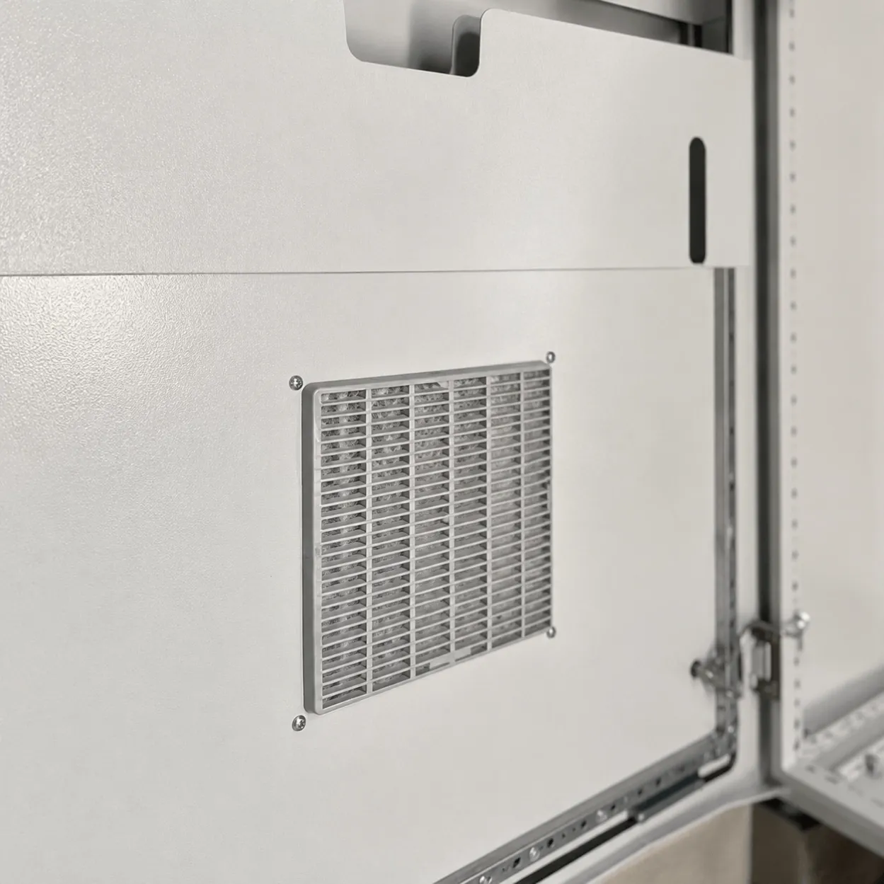
Higher enclosure protection or internal separation can affect heat dissipation. Fans or air conditioning should not be added without considering maintenance, filters, condensation, loss of cooling, and enclosure protection.
Spare Capacity and Future Extension
A request for “20% spare” should identify what type of spare capacity is required.
Possible requirements include:
- Spare outgoing feeder compartments
- Installed spare breakers
- Busbar current reserve
- Spare CT and metering provisions
- Spare control terminals
- Spare auxiliary contacts
- Future bus-coupler provision
- Spare cable-entry space
- Future panel extension
- Physical space in the electrical room
- Thermal capacity
- Additional communication ports
A spare compartment sized for a small MCCB may not support a future ACB feeder. Likely future loads should therefore be identified during design.
Applicable Standards and Verification
For IEC-oriented low-voltage projects, PCC panels commonly fall within the scope of:
- IEC 61439-1, general rules for low-voltage switchgear and controlgear assemblies
- IEC 61439-2, power switchgear and controlgear assemblies
- IEC 60947 series for relevant switchgear and controlgear devices
- IEC 60529 for enclosure IP classification
- Project-specific electrical and installation requirements
The project should define:
- Applicable standard edition
- Assembly classification
- Original manufacturer
- Assembly manufacturer
- Design-verification basis
- Routine-verification scope
- Short-circuit rating
- Temperature-rise verification
- Internal separation
- IP rating
- Environmental conditions
- Documentation
- Certification or witness requirements
A statement that individual breakers comply with IEC standards does not demonstrate that the complete PCC assembly has been designed and verified to IEC 61439.
For North American projects, PCC is not normally the formal product-category name. Depending on construction and intended use, the equipment may instead be classified as a switchboard, switchgear assembly, panelboard, or another listed product. The applicable UL or NEC route must be confirmed before quotation.
Build-to-Print and Design-and-Build Projects
Build-to-Print PCC Panel
This route is suitable when the customer or electrical consultant provides an approved:
- SLD
- GA drawing
- Busbar design
- Feeder schedule
- Protection study
- BOM
- Control schematics
- Metering diagram
- Cable schedule
- Test plan
UniRegal reviews the package for manufacturability, component availability, drawing conflicts, and agreed production requirements before manufacturing.
Design-and-Build PCC Panel
This route is suitable when the customer has a confirmed electrical requirement but has not completed the manufacturing package.
The project should begin with source data, SLD, fault level, feeder schedule, protection requirements, room layout, environmental conditions, and applicable standards.
Design approval stages should be defined before components and enclosures are released for production.
Factory Acceptance Testing
The FAT should follow an approved inspection and test plan.
Depending on contractual scope, it may include:
Document Review
- Approved SLD
- GA drawing
- Feeder schedule
- BOM
- Control schematics
- Metering diagram
- Protection settings
- Nameplate data
Mechanical and Construction Inspection
- Panel dimensions
- Shipping sections
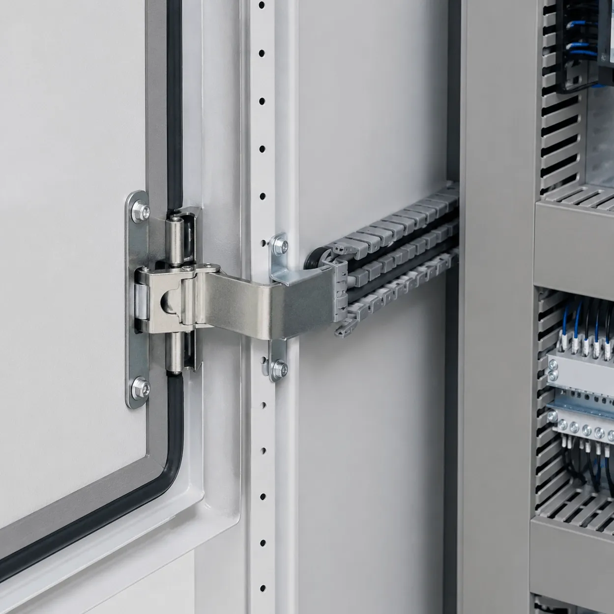
- Enclosure construction
- Internal separation
- Breaker and component installation
- Busbar supports
- Cable chambers
- Barriers and shutters
- Door interlocks
- Lifting provisions
- Labels and warning signs
Electrical Verification
- Protective bonding continuity
- Internal wiring verification
- Control-circuit continuity
- Insulation-resistance testing where applicable
- Dielectric testing where specified
- Phase sequence
- Neutral and earth arrangement
- Metering circuits
- CT wiring and polarity
- Auxiliary power supplies
Functional Testing
- Breaker mechanical operation
- Electrical opening and closing
- Trip-circuit test
- Bus-coupler interlocking
- Incomer interlocking
- Source-status simulation
- Meter configuration
- Indication and alarms
- Local and remote control
- SCADA communication
- Protection-relay secondary injection where specified
- Approved operating sequence
Final Review
- Drawing consistency
- Breaker and relay settings
- FAT report
- Punch-list closure
- Packing and shipping-section identification
The exact tests, methods, acceptance criteria, witness requirements, and records must be agreed before manufacturing.
What the PCC FAT Cannot Prove
A factory test cannot independently prove:
- Actual site fault level
- Correctness of the customer’s system study
- Complete upstream and downstream selectivity
- Field cable ampacity
- Site earthing effectiveness
- Busduct alignment after installation
- Field termination quality
- Room ventilation
- Actual full-load performance
- Site source-transfer behavior
- Final statutory acceptance
These items require approved engineering information, installation checks, site testing, or review by the responsible electrical authority.
Retrofit and Replacement PCC Panels
Replacing an existing PCC requires more planning than copying its external dimensions.
The review may need:
- Existing SLD
- Existing protection study
- Transformer and generator data
- Fault level
- Existing breaker settings
- Feeder and cable schedule
- Busbar data
- CT ratios
- Metering and SCADA interfaces
- Panel room dimensions
- Cable trench
- Busduct connections
- Current maintenance access
- Available outage
- Temporary power requirements
- Cutover sequence
- Lifting and transport route
- Future expansion requirement
When existing documentation is unreliable, a field survey and shutdown inspection may be required. The replacement panel should not be manufactured from photographs alone.
Common PCC Procurement Mistakes
Procurement Mistake | Possible Consequence |
|---|---|
Requesting a quotation from voltage and current only | The panel may not match the actual source or feeder architecture |
Calling the PCC an HT panel without defining the voltage | The supplier may quote the wrong equipment category |
Assuming the ACB breaking capacity equals panel withstand | The complete assembly rating may remain unverified |
Leaving bus-coupler logic until commissioning | Source interlocking may require major control revisions |
Selecting Form 4 without defining the maintenance objective | The panel may become larger and more expensive without solving the real need |
Omitting transformer impedance | The fault-level basis may be incorrect |
Supplying no room layout | Access, transport, cable trench, or extension problems may appear |
Comparing busbar material without comparing verified design | The comparison may ignore dimensions, joints, losses, and temperature rise |
Requesting spare space without defining future feeders | The spare section may not support the future breaker |
Approving the cabinet before cable data is available | Termination and bending space may be insufficient |
Treating FAT as proof of site performance | Installation and system-level issues may remain unresolved |
Comparing only breaker brands | Verification, protection, room fit, and testing differences are missed |
What Affects PCC Panel Price and Lead Time?
The main factors include:
- Rated current
- Fault withstand requirement
- Number and size of busbar sections
- Copper or aluminium busbar
- Number of incomers
- Bus-coupler arrangement
- ACB and MCCB quantity
- Fixed or draw-out construction
- Internal separation
- Protection relays and trip units
- CTs and metering
- SCADA communication
- Cable chambers
- Busduct interfaces
- Enclosure dimensions
- Indoor or outdoor construction
- Shipping sections
- Applicable standard
- Design-verification basis
- FAT and witness testing
- Component brand and availability
- Documentation requirements
- Site commissioning scope
Two PCC quotations may use the same breaker brand but include different fault ratings, forms of separation, busbar systems, verification, metering, access, and testing. These differences must be compared before price.
How to Compare PCC Panel Manufacturer Quotations
Scope Item | Buyer Question |
|---|---|
Assembly Classification | Is this a low-voltage PSC assembly or another product type? |
SLD | Is the quotation based on the latest approved SLD? |
Rated Current | What continuous-current basis and service conditions are included? |
Fault Rating | What short-time and peak withstand values are included? |
Busbar | What material, arrangement, rating, joint system, and verification basis are used? |
Incomers | Are breakers fixed or draw-out, and which trip functions are included? |
Bus Coupler | What interlocking and operating philosophy is included? |
Feeders | Are breaker frames, poles, settings, CTs, and cable chambers defined? |
Separation | Which form of separation and terminal arrangement are included? |
Protection | Is the protection study included, supplied by the customer, or excluded? |
Metering | Which meters, CT classes, accuracy, and communication functions are included? |
Room Fit | Have the electrical room, transport, access, and extension requirements been reviewed? |
Verification | What design-verification evidence and routine tests are included? |
FAT | Which functional, protection, metering, and interlock tests will be witnessed? |
Documentation | Are approved and as-built documents, settings, and test records included? |
Certification | Is the quotation offering compliance consideration or an official certificate or mark? |
Site Work | Are installation, busduct alignment, settings, commissioning, and SAT included? |
Frequently Asked Questions
What is a PCC panel?
A PCC panel is a central low-voltage power distribution assembly used to receive power from a transformer, generator, utility source, or upstream switchgear and distribute it to MCC panels, distribution boards, and major electrical loads.
What is the full form of PCC panel?
PCC panel usually means Power Control Centre panel in British English or Power Control Center panel in American English. The abbreviation describes its central power-distribution role but does not by itself define the applicable electrical standard.
Is “PCC control panel” the correct term?
It is a commonly searched phrase, although the word “control” already appears in Power Control Centre. “PCC panel” or “Power Control Centre panel” is generally clearer for industrial electrical distribution.
Is a PCC panel an HT or LT panel?
This page covers low-voltage PCC panels. Under IEC 61439-2, a power switchgear and controlgear assembly may operate up to 1,000 V AC or 1,500 V DC. Medium-voltage switchgear requires a different product and standard path.
What is the difference between MCC and PCC panel?
The PCC receives and distributes central plant power through incomers, busbars, bus couplers, and outgoing feeders. The MCC normally receives one of those feeders and controls individual motors using starters, overload protection, soft starters, or VFDs.
What is the full form of PCC and MCC panel?
PCC means Power Control Centre or Power Control Center. MCC means Motor Control Centre or Motor Control Center. A plant may use the PCC for central distribution and the MCC for motor control.
Do industrial plants need both PCC and MCC panels?
Many do. The PCC distributes power from the main source to different plant sections, while one or more MCC panels control motors in production, utility, HVAC, pumping, or process areas. The actual requirement follows the approved SLD.
What is the difference between a PCC panel and an MDB?
The terms may overlap. On this website, PCC refers to industrial central distribution with transformer incomers, bus couplers, ACBs, high-current busbars, internal separation, and downstream MCC feeders. MDB addresses more general building or facility distribution.
What information is required for a PCC panel quotation?
Provide the SLD, transformer and generator data, available fault current, incomer and feeder schedules, bus-coupler philosophy, protection study, earthing system, cable or busduct information, room layout, environmental conditions, applicable standards, and FAT requirements.
Can you quote a PCC panel from the transformer kVA rating?
The transformer rating is not enough. The design also requires secondary voltage, impedance, number of transformers, parallel-operation conditions, connection method, available fault current, load demand, protection philosophy, and feeder schedule.
How is PCC busbar size selected?
Busbar design depends on rated current, material, temperature rise, short-circuit withstand, joint design, support spacing, enclosure, ambient conditions, internal separation, harmonics, and the verified assembly system. Current alone is insufficient.
Is copper busbar always better than aluminium?
Not automatically. Both can be used in a properly engineered and verified assembly. Buyers should compare dimensions, joints, thermal performance, weight, maintenance, corrosion considerations, verified ratings, availability, and total cost.
What is a bus coupler in a PCC panel?
A bus coupler connects or separates two bus sections. Its control logic determines when the sections may operate independently or together. The arrangement requires approved interlocking, source conditions, protection, and operating procedures.
Can two PCC incomers operate in parallel?
Only when the sources, breakers, busbars, protection, synchronization, and operating philosophy have been specifically designed for parallel operation. A general dual-incomer request does not automatically permit paralleling.
What is Form 4b separation in a PCC panel?
Form 4b is a high level of internal separation involving functional units and their associated terminals. The precise construction must follow the applicable standard and verified assembly design. It should be specified according to maintenance and isolation needs.
What is the difference between breaker breaking capacity and PCC fault rating?
Breaking capacity applies to the individual breaker. The PCC rating applies to the complete assembly under defined conditions and also depends on the busbar system, supports, connections, functional units, and verified design.
Does IEC 61439 require a type-tested PCC panel?
IEC 61439 uses design verification and routine verification terminology. Buyers should request the applicable verification evidence rather than rely only on the older general phrase “type-tested panel.”
What does PCC panel FAT include?
The FAT may cover documents, construction, busbars, internal wiring, protective bonding, insulation tests, breaker operation, bus-coupler interlocks, meters, CT circuits, protection relays, local and remote control, communication, and final records.
Can a PCC FAT prove the complete plant distribution system is correct?
No. FAT can verify the panel against approved documents. It cannot independently verify the site fault level, upstream and downstream coordination, field cables, earthing, busduct installation, room ventilation, or final operating conditions.
Can an existing PCC panel be replaced without drawings?
Replacement may be possible after a field survey and planned shutdown inspection. The source, feeders, cables, busduct, breaker settings, CTs, control interfaces, room dimensions, cutover procedure, and unidentified connections must be confirmed first.
Request a PCC Panel Quotation
Please send:
- Approved or preliminary single-line diagram
- Transformer and generator data
- System voltage, phase, and frequency
- Available fault current
- Incomer schedule
- Bus-coupler philosophy
- Outgoing feeder schedule
- Load and demand information
- Protection and selectivity study
- Earthing system
- Metering and SCADA requirements
- Cable or busduct information
- Electrical room layout
- Internal-separation requirement
- Ambient and installation conditions
- Applicable standards
- FAT and witness requirements
- Quantity and destination country
UniRegal will review the source, busbar, protection, feeder, installation, verification, and testing requirements before defining the PCC panel scope.
Related Products: