
Jul 18, 2026Case Studies
Motor Control Panel Verification for Safe and Reliable Industrial Motor Operation
The case study recording Motor Control Panel Verification for Safe and Reliable Industrial Motor Operation.
Motor Control Panel Verification for Safe and Reliable Industrial Motor Operation
A motor control panel does not need to be complex to require serious engineering attention. Even a basic panel with MCCB protection, MCB circuits, phase indication, ON/OFF status lamps, rotary isolation, and neat wiring must be verified before delivery. This case documents the engineering checks behind a completed motor control panel prepared for reliable industrial operation.
Project Snapshot
Item | Description |
|---|---|
Industry | General Industrial Application |
Application | Motor operation and local electrical control |
Project Type | Motor control panel assembly and QA verification |
Location | Confidential |
Products | MCCB, MCBs, RYB phase indication lamps, ON/OFF indication, rotary isolator switch |
Services | Panel assembly, wiring, component verification, continuity testing, functional testing |
Result | Completed motor control panel released as ready for operation after QA checks |
Project Overview
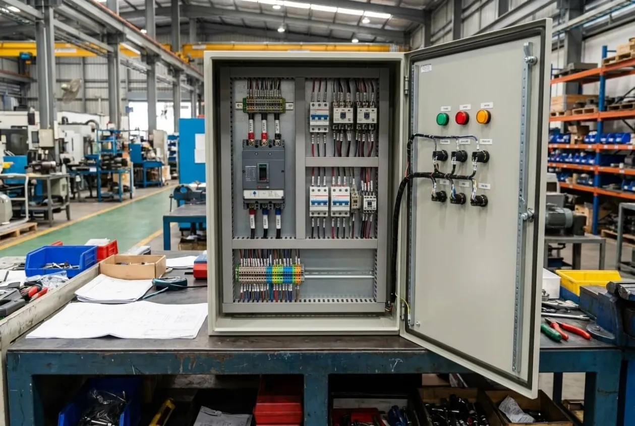
This project involved the completion of a motor control panel[¹] designed for safe and reliable industrial motor operation. The panel included one main MCCB[²] for incoming power protection and isolation, three MCBs[³] for individual circuit protection, RYB phase indication lamps, ON/OFF status indication, a rotary isolator switch, and organized internal wiring for maintenance access.
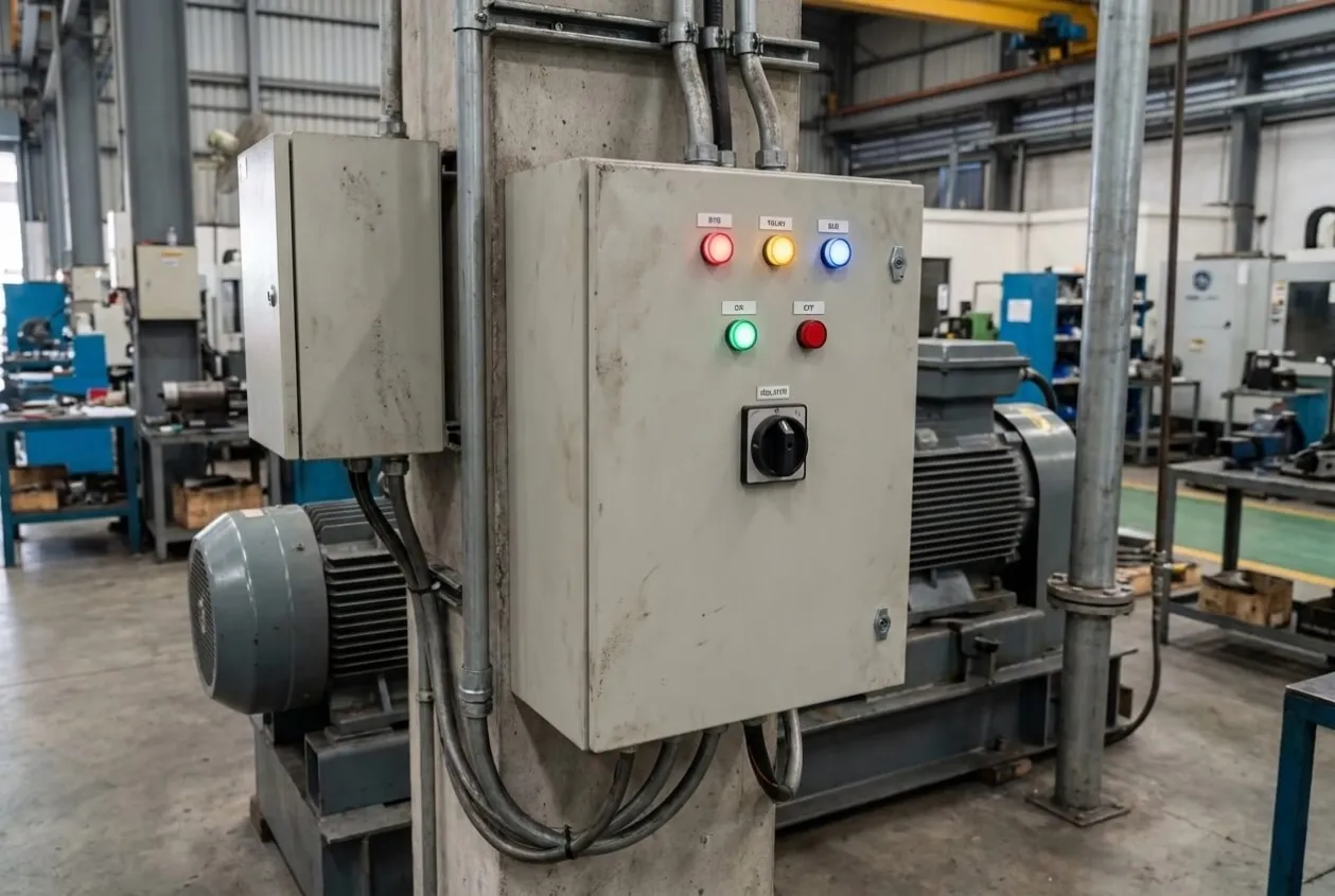
The customer needed a panel that could arrive at the site ready for connection, not a cabinet that still needed interpretation. That was the real pressure behind this job. The panel was not large or technically complicated, but it still had to be clear enough for the site electrician, safe enough for the operator, and reliable enough for daily industrial use while following recognized IEC low-voltage switchgear standards[⁴].
At the workshop stage, it is easy to think a panel is finished once the wiring looks neat and all devices are mounted. I do not agree with that. A control panel is not finished when it looks complete. It is finished when its protection, indication, isolation, wiring, and operating functions have been tested together.

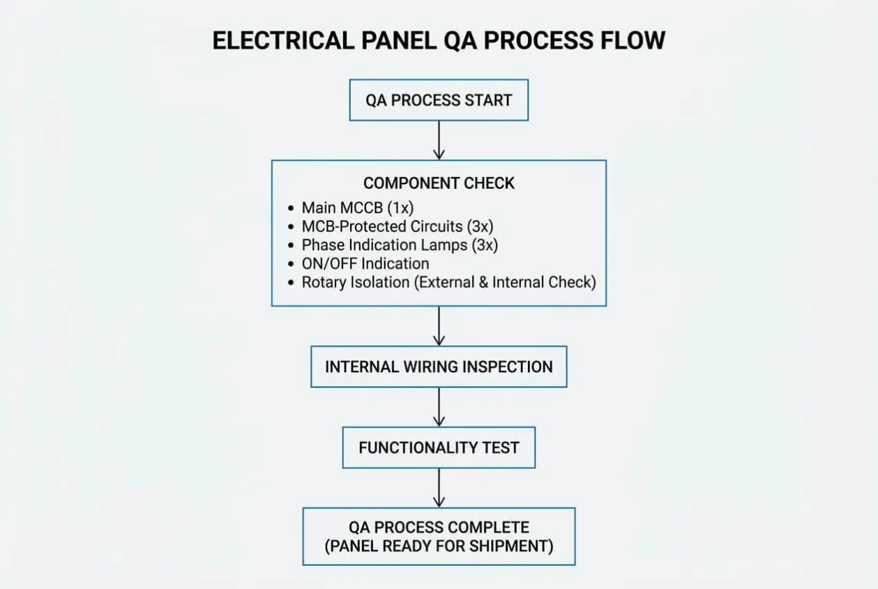
That was the purpose of the QA process. Before delivery, the panel went through component verification, wiring inspection, continuity testing, and functional testing. These checks turned the cabinet from an assembled panel into a delivery-ready motor control solution.
Customer Challenge
From the customer’s perspective, the requirement was practical. The motor control panel needed to operate safely, be easy to understand, and allow maintenance technicians to troubleshoot quickly when needed.
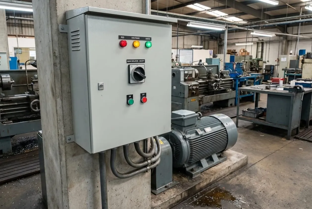
The site team did not need a complicated system. They needed a dependable one. When the panel arrived onsite, the electrician had to identify the incoming supply, branch circuits, indication wiring, isolator function, and field terminals without wasting time. The operator had to look at the door and understand whether power was available and whether the system was ON or OFF.
Several concerns had to be addressed:
- Incoming power needed proper protection and isolation.
- Individual circuits required dedicated protection.
- Operators needed clear visual indication of phase availability.
- ON/OFF status had to be visible without opening the panel.
- Maintenance personnel needed a safe isolator for service work.
- Internal wiring had to be neat, traceable, and easy to inspect.
- The completed panel had to be tested before delivery.
If these risks were ignored, the panel could create problems immediately after installation. A wrong MCB connection could leave a circuit unprotected. A phase lamp wiring error could give misleading information. Poor internal wiring could make maintenance slow and unsafe. A loose connection could overheat during operation. A rotary isolator wired incorrectly could create a serious safety risk.
Small panels often create big frustration because everyone assumes they are simple. But on site, even one wrong indication lamp or one unclear terminal can stop progress while several people wait around the cabinet.
In industrial applications, operators often judge a panel by whether it works. Engineers must judge it by whether it works safely, clearly, and repeatedly.
Engineering Review
The engineering review focused on protection, isolation, indication, wiring arrangement, and QA readiness.
The main MCCB was the first important device. It provided incoming power protection and a clear means of isolation for the panel. For any motor control panel, the incoming protective device must be suitable for the expected load, cable size, operating environment, and fault protection philosophy. Even when the exact electrical rating is confidential, the principle remains the same: the incoming device must protect the panel and support safe operation.
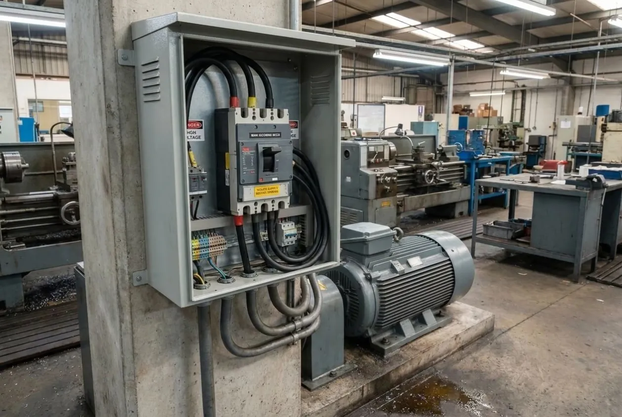
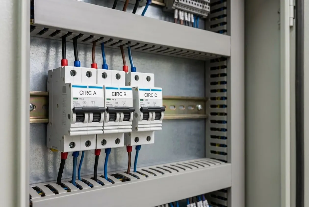
The three MCBs provided individual circuit protection. This is a good design practice because auxiliary circuits, control circuits, indication circuits, or branch loads should not all depend on one common protection point. When circuits are separated properly, a fault in one branch is easier to identify and less likely to affect unrelated functions.
The RYB phase indication lamps were also important. These lamps give operators and technicians a quick visual confirmation that the three incoming phases are available. This is especially useful before motor operation, during troubleshooting, or after power restoration.
ON/OFF status indication was included to show operating condition clearly. A panel should communicate its state without forcing the operator to open the door or measure voltage. Clear indication reduces mistakes.
The rotary isolator switch added another layer of safe operation. It allowed controlled isolation and helped maintenance personnel work with more confidence. In my view, isolation devices should always be reviewed carefully because they are directly related to human safety.
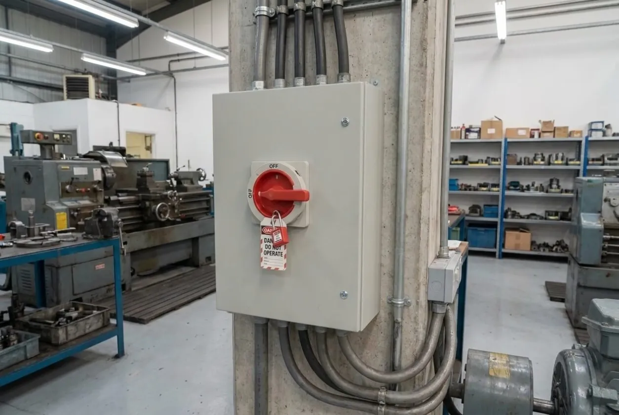
The wiring arrangement was another major review point. Neat wiring is not only about appearance. It affects heat dissipation, inspection, troubleshooting, and long-term reliability. Poor wire routing can hide loose terminals, make fault tracing difficult, and increase the chance of accidental damage during maintenance.
A simplified engineering review table is shown below:
Review Item | Engineering Question | Risk if Ignored |
|---|---|---|
Main MCCB | Is incoming power protected and isolatable? | Unsafe fault condition or difficult shutdown |
MCB circuits | Are branch circuits individually protected? | Faults spread across multiple circuits |
RYB lamps | Do lamps correctly show phase availability? | Misleading power status indication |
ON/OFF indication | Can operators confirm status quickly? | Operator confusion during operation |
Rotary isolator | Is isolation clear and safe? | Maintenance safety risk |
Internal wiring | Are wires routed, ferruled, and labeled clearly? | Slow troubleshooting and loose connections |
Terminal access | Can field connections be made safely? | Installation delay or wiring mistakes |
QA test process | Has the panel been tested before delivery? | Site rework and commissioning delay |
The review confirmed that this panel should be treated as a safety and reliability product, not just an assembled electrical box.
Critical Engineering Decision
The critical engineering decision in this project was to make QA verification part of the completion definition.
Many panel projects fail at this point. The assembly team finishes wiring, the panel looks clean, the door devices are installed, and everyone feels the work is complete. But visual completion is not electrical completion.
There were two possible approaches.
- Complete assembly, check the appearance, and release the panel. This approach is fast, but it depends too much on assumption. It assumes every wire is correct, every device is suitable, every terminal is tight, and every indication works as intended.
- Complete a structured QA process before delivery. This included component verification, wiring inspection, continuity testing, and functional testing. This approach takes more time, but it reduces site risk.
We selected the second approach.
The reason was simple. A motor control panel is installed to control energy. It must not leave the workshop based only on appearance.
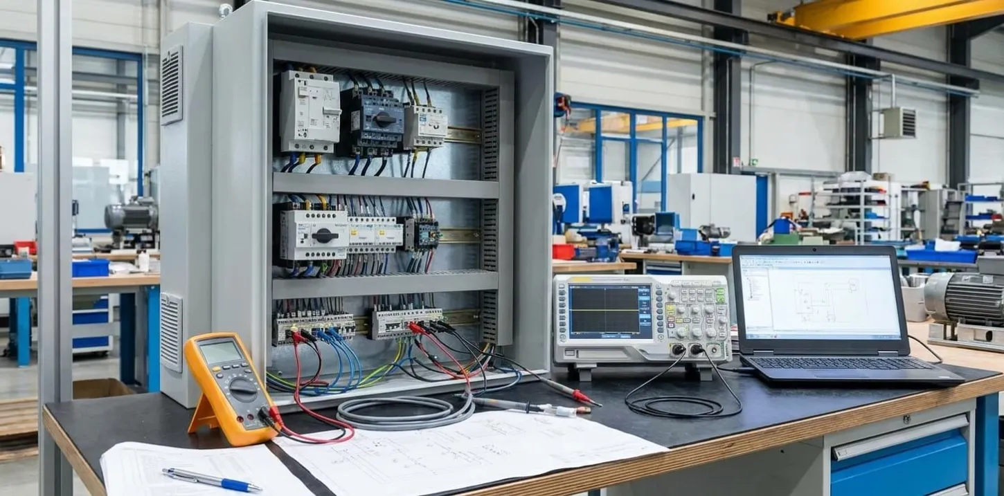
For this panel, the QA process gave us a controlled moment to check one main MCCB, three MCB-protected circuits, three phase indication lamps, ON/OFF indication, rotary isolation, and internal wiring before the cabinet left our hands.
That decision avoided several common site problems:
- Wrong indication behavior.
- Incorrect branch circuit wiring.
- Loose terminals.
- Confusing field termination.
- Poor drawing-to-panel consistency.
- Unclear isolation function.
- Site rework during installation.
In panel building, the best time to correct a problem is before packing. After shipment, even a small correction becomes more expensive, more visible, and more disruptive.
Solution Delivered
The delivered solution was a completed motor control panel prepared for safe and reliable motor operation.
The panel included one main MCCB on the incoming side. This provided protection and isolation for the incoming power supply. The MCCB was positioned for clear access and operation.
Three MCBs[⁵] were installed for individual circuit protection. This helped separate circuit functions and made future troubleshooting easier. If one branch circuit has a fault, the technician can identify the affected area more quickly instead of treating the entire panel as one unknown problem.
RYB phase indication[⁶] lamps were installed on the panel door to show the availability of the three incoming phases. This gives operators an immediate visual reference before operation. It also helps the maintenance team confirm supply condition without opening the panel immediately.
ON/OFF status indication[⁷] was provided so that the motor or control status could be understood clearly. In many industrial environments, this simple indication prevents confusion between energized, stopped, available, and running states.
A rotary isolator switch[⁸] was included for safe operation and maintenance. This gave the operator or technician a physical isolation method and improved confidence during service activities while following recognized IEC 61439[⁹] design principles.
Inside the panel, wiring was arranged neatly using organized routes and clear separation. Wires were dressed properly, and the internal layout allowed maintenance personnel to inspect devices without unnecessary difficulty.
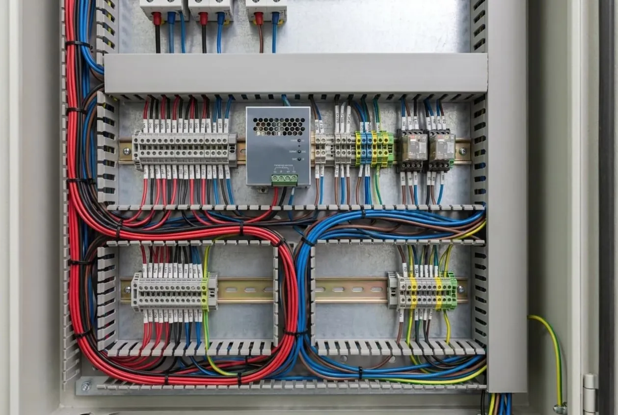
The final panel was not designed to impress with complexity. It was designed to perform basic motor control functions correctly and safely. That is often the most important requirement in industrial electrical work.
Before Shipment Verification
Before shipment, the panel went through QA verification. This section is important because it shows how a motor control panel moves from assembled condition to delivery-ready condition.
The verification process included:
Verification Activity | Why It Mattered |
|---|---|
Component verification | Confirmed installed devices matched the approved design |
MCCB inspection | Checked incoming protection and isolation arrangement |
MCB inspection | Confirmed branch protection devices were installed correctly |
Wiring inspection | Verified wire routing, termination, ferrules, and labels |
Continuity testing | Confirmed circuits were electrically continuous where required |
Insulation and separation review | Checked basic safety separation and wiring condition |
Phase lamp test | The verified RYB indication worked correctly |
ON/OFF indication test | Confirmed status lamps responded as expected |
Rotary isolator test | Checked mechanical operation and electrical function |
Terminal check | Confirmed terminal tightness and identification |
Functional testing | Proved the panel performed its intended control functions |
Documentation review | Confirmed drawings and labels matched the panel |
Packing inspection | Protected the panel during transport |
During QA, the team checked not only whether the panel could be energized, but also whether the panel communicated correct information to the operator. This is an important point. A lamp that turns on at the wrong time is worse than no lamp, because it gives false confidence.
Continuity testing confirmed that the circuits were wired correctly before operation. This helped identify open circuits, wrong connections, and termination mistakes.
Functional testing confirmed that the panel operated as expected. This included checking the response of indication devices, isolation functions, and protected circuits.
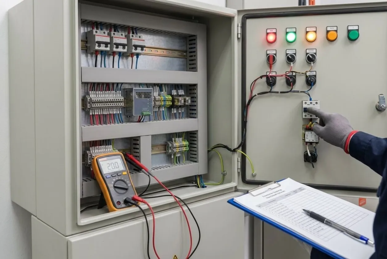
The internal wiring was also inspected carefully. Neat wiring supports long-term reliability, but it must also be electrically correct. A clean wire duct does not guarantee correct wiring. That is why visual inspection and electrical testing must work together.
The panel passed QA verification and was released as completed and ready for operation.
Project Results
The motor control panel was completed, tested, and prepared for operation.
The result was practical and measurable. Before release, the QA team verified:
- 1 main MCCB for incoming protection and isolation.
- 3 MCB-protected individual circuits.
- 3 RYB phase indication lamps.
- 2 status indication functions: ON and OFF.
- 1 rotary isolator switch for safe operation.
- 4 core QA stages: component verification, wiring inspection, continuity testing, and functional testing.
The completed panel delivered six verified operating functions: incoming isolation, branch circuit protection, three-phase indication, ON/OFF status display, rotary isolation, and maintainable internal wiring.
This gave the customer a delivery-ready panel rather than only an assembled cabinet. The site electrician would not need to guess whether the indication lamps were correctly wired. The maintenance team would not need to trace unclear internal wiring on the first day. The operator would have clear visual status from the panel door.
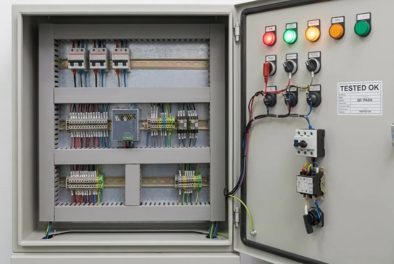
The project also reinforced an important engineering habit: basic panels still require disciplined checks. The absence of PLCs, HMIs, or communication networks does not remove the need for proper verification.
In fact, many basic control panels are used in tough industrial environments by operators who need simple, dependable functions. These panels must be easy to understand, easy to maintain, and safe to operate.
This panel achieved that objective by combining practical component selection with a structured QA process.
Engineering Notes from Natalie
I have always believed that neat wiring tells only half the story.
A clean control panel gives a good first impression, but it does not prove that the panel is ready. I still want to see the test records. I want to see the phase lamps tested, the isolator checked, the MCB circuits verified, and the terminals inspected.
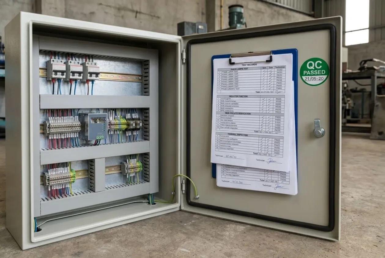
For motor control panels, operators depend on simple things. They look at a lamp and decide whether power is available. They use an isolator and trust that the circuit is safe. They open the panel and expect wire numbers to match the drawing.
When these simple things are wrong, confidence disappears quickly.
That is why I like structured QA, even for smaller panels. It prevents the team from saying “it looks finished” too early. A panel is ready only when its protection, indication, wiring, and operation have been verified.
Good engineering is often quiet. It shows up later when the site team has fewer problems.
Lessons Learned
1. A basic motor control panel still needs full QA
Simple panels can still create safety and reliability problems if wiring, protection, indication, or isolation is not verified before delivery.
2. Incoming and branch protection should be reviewed separately
The main MCCB protects and isolates the incoming supply, while MCBs protect individual circuits. This separation improves fault handling and maintainability.
3. Indication lamps must be tested, not assumed
RYB phase lamps and ON/OFF status lamps help operators understand the panel condition. Incorrect indication can lead to wrong decisions.
4. Rotary isolation improves maintenance safety
A clear isolation method helps technicians work with more confidence and reduces unsafe maintenance practices.
5. Neat wiring must also be traceable
Good wire dressing is useful only when wire numbers, terminals, and drawings match. Maintenance depends on both organization and accuracy.
6. Functional testing should happen before delivery
A panel should not reach the site before its basic functions have been tested. Workshop testing is faster, safer, and easier than field troubleshooting.
Key Takeaways
✔ A motor control panel is complete only after protection, indication, isolation, and wiring are verified.
✔ QA testing prevents simple wiring or indication errors from becoming site problems.
✔ Neat, traceable wiring improves long-term maintenance and operator confidence.
Need Similar Support?
If you are preparing a motor control panel, pump starter panel, MCC section, or local control cabinet, send us:
✓ Single Line Diagram
✓ Motor List
✓ Control Philosophy
✓ Voltage
✓ Installation Environment
Even a short engineering review before fabrication can identify protection, isolation, indication, wiring, labeling, and QA risks while they are still easy to correct.
Related Articles:
The Hidden Wiring Problems That Cause Startup Delays in OEM Projects: An Actionable Prevention Guide