
MCC Panels
Main Distribution Board Manufacturer
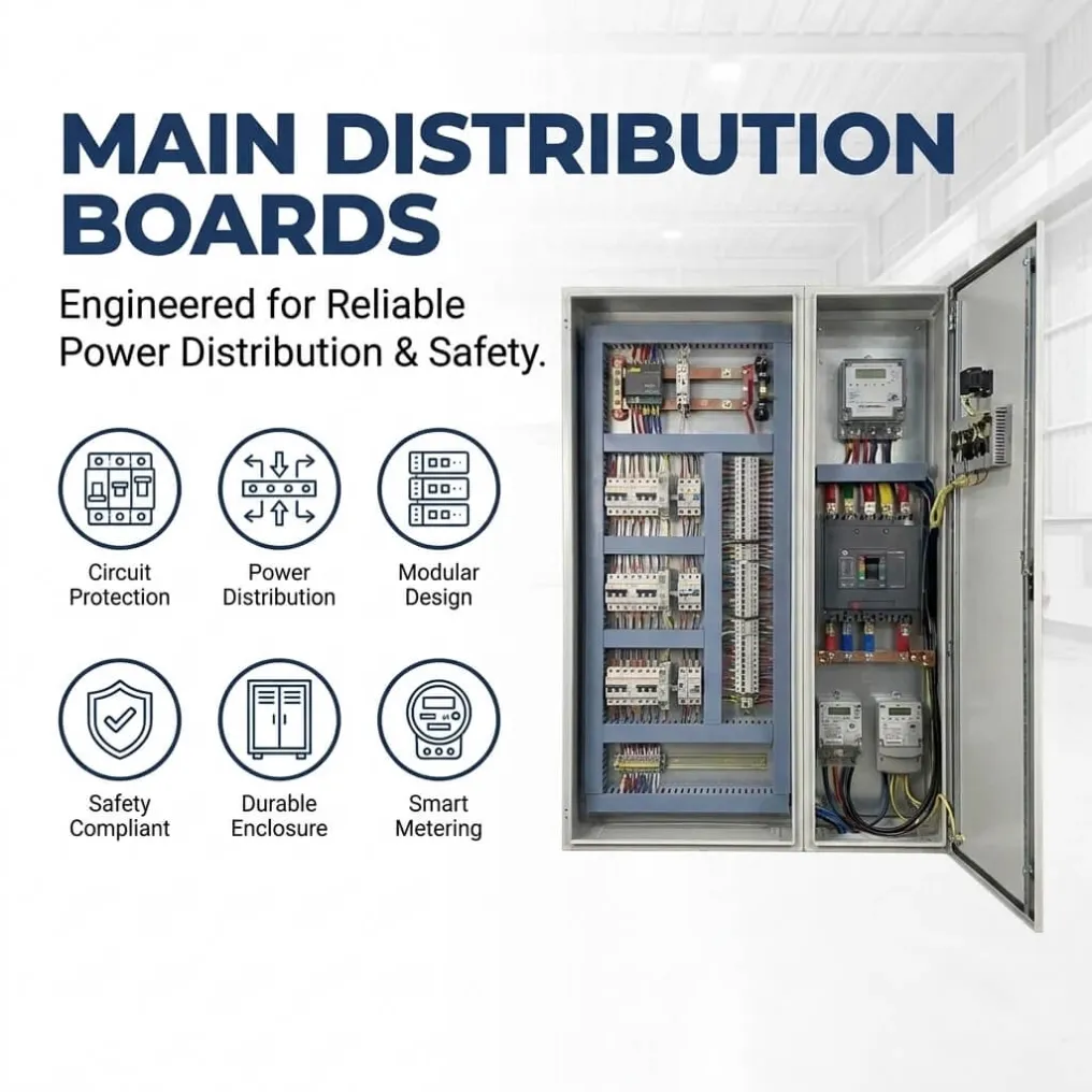
UniRegal supplies custom main distribution boards for commercial and industrial power receiving, metering and feeder distribution. Send your SLD, load schedule, incomer rating, outgoing circuits and cable-entry requirements.
Main Distribution Board for Industrial and Commercial Power Distribution
UniRegal supplies custom low-voltage Main Distribution Boards for factories, commercial buildings, utilities, water treatment facilities, HVAC systems and infrastructure projects.
Each MDB is configured around the incoming power source, total demand, available fault current, outgoing feeder schedule, protection strategy, cable arrangement, metering requirements and planned expansion.
The objective is not simply to fit breakers into an enclosure. A properly specified Main Distribution Board must distribute power without allowing a downstream fault, overloaded feeder, unsuitable busbar or installation problem to affect the entire facility unnecessarily.
Send us your single-line diagram and feeder schedule for technical review.
Quick Answer
A Main Distribution Board, commonly abbreviated as MDB, is the primary low-voltage assembly that receives power from a transformer, generator or utility supply and distributes it to downstream electrical panels and major loads.
A typical distribution path is:
Transformer / Generator / Utility Supply → Main Distribution Board → SMDB / MCC / Distribution Board → Final Loads
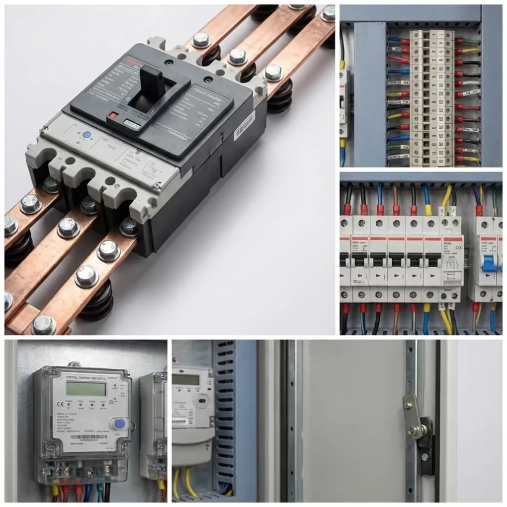
The MDB normally contains the main incomer, busbar system, outgoing circuit breakers, metering, neutral and earth bars, protection devices and cable-termination sections.
What a Main Distribution Board Does
The Main Distribution Board forms the main connection between the incoming electrical source and the facility’s downstream distribution system.
Depending on the project, it may provide:
- Main incoming isolation
- Short-circuit and overload protection
- Distribution to multiple outgoing feeders
- Busbar power transfer
- Normal and emergency source management
- Electrical metering and monitoring
- Surge protection
- Earth-fault protection
- Neutral and earthing arrangements
- Feeder isolation
- Cable termination
- Spare capacity for future loads
Because the MDB is positioned upstream of major plant loads, an incorrect rating or protection decision can affect far more than one circuit.
Buyer Decision Information
A Main Distribution Board should not be selected only by total current or enclosure size. The following decisions must be made before the board can be properly specified.
Decision Point | Why It Matters | Information to Confirm |
|---|---|---|
Incoming Power Source | The architecture changes for transformer, generator, utility or multiple supplies | Source quantity, voltage, frequency and earthing system |
Maximum Demand | Determines incomer, busbar and thermal requirements | Connected load, diversity, demand and future growth |
Available Fault Current | Determines the required short-circuit rating | Prospective fault current at the MDB location |
Main Incomer | Determines isolation and protection capability | ACB, MCCB, switch disconnector or fuse switch |
Busbar System | Affects current capacity, temperature rise and short-circuit withstand | Material, rating, neutral size and earth bar |
Outgoing Feeders | Determines breaker quantity, cable space and board layout | Feeder rating, load name, poles, cable and trip settings |
Protection Selectivity | Determines whether a downstream fault trips only the affected feeder | Breaker models, settings and coordination study |
Cable Entry | Affects enclosure layout and installation work | Top, bottom, front or rear access |
Metering | Determines what the operator or BMS can monitor | CT ratio, energy data, alarms and communication |
Source Changeover | Affects normal, generator and emergency supply operation | ATS, bus coupler, interlocks and transfer logic |
Installation Environment | Determines enclosure construction and thermal design | Indoor, outdoor, heat, dust, humidity and corrosion |
Expansion Capacity | Determines whether future feeders can be added without rebuilding | Spare ways, busbar capacity and physical compartments |
Do Not Select an MDB by Connected Load Alone
The total connected load is not the same as the maximum electrical demand.
An MDB rating should consider the simultaneous operating load, applicable diversity or demand factor, transformer or generator capacity, planned expansion, load characteristics and applicable project requirements.
Simply adding every downstream breaker rating can produce an unrealistic total. Selecting the board only from current operating demand can create the opposite problem by leaving no practical allowance for expansion or operating changes.
The review should distinguish between:
- Total connected load
- Calculated maximum demand
- Main incomer rating
- Busbar continuous-current rating
- Group loading and temperature rise
- Generator operating capacity
- Essential and non-essential loads
- Reserved capacity for future feeders
These values may be related, but they are not automatically identical.
Main Distribution Board vs Other Electrical Panels
Panel Type | Main Function | Position in the Electrical System |
|---|---|---|
Main Distribution Board | Receives and distributes the main low-voltage supply | Main upstream distribution point |
Sub Main Distribution Board | Distributes power to a floor, zone, workshop or load group | Downstream of the MDB |
Distribution Board | Supplies final lighting, socket or small-power circuits | Close to final loads |
MCC Panel | Distributes and controls power for multiple motors | Motor-control section downstream of MDB |
Power Control Panel | Controls or distributes power for a specific machine or process | Application-specific |
Main Switchboard | Main service or distribution assembly, often used for larger systems | May overlap with the term MDB depending on the market |
The terms MDB and Main Switchboard are sometimes used interchangeably. The final product description should follow the project specification, applicable standard and required construction rather than rely only on the name.
Main Incomer and Source Configurations
MCCB Incomer
An MCCB incomer may be suitable for Main Distribution Boards that require adjustable protection in a compact configuration.
The final selection depends on current rating, breaking capacity, required trip functions, maintenance approach and coordination with downstream breakers.
ACB Incomer
An Air Circuit Breaker may be selected when the project requires higher current capacity, advanced protection settings, draw-out construction, remote operation or a more detailed selectivity strategy.
An ACB is not automatically required simply because the enclosure is large. The decision must follow the electrical system study and operational requirements.
Switch Disconnector
A switch disconnector provides isolation but does not necessarily provide the same overload and short-circuit protection functions as a circuit breaker.
It may be used when suitable protection is already provided upstream, subject to the system design and applicable requirements.
Dual Incomer and Bus Coupler
Projects with two transformers, two utility supplies or normal and standby sources may require dual incomers and a bus coupler.
The operating philosophy must define whether the sources can run in parallel, whether the coupler is normally open or closed, and which electrical and mechanical interlocks are required.
ATS or Generator Incomer
Where generator backup is required, the MDB may receive power through an Automatic Transfer Switch or include a source-transfer arrangement.
The transfer sequence, generator capacity, essential loads, load shedding and return-to-normal operation must be confirmed before manufacturing.
Short-Circuit Rating: Why Current Rating Is Not Enough
An MDB can have the correct continuous-current rating and still be unsuitable for the installation if its short-circuit rating is too low.
The available fault current depends on factors such as:
- Transformer rating and impedance
- Distance from the transformer
- Cable or busduct impedance
- Parallel power sources
- Generator contribution
- Upstream protection
- System voltage
The required breaking and withstand ratings must be based on the prospective fault current at the MDB installation point.
Depending on the design and applicable standard, the specification may refer to values such as:
- Circuit-breaker breaking capacity
- Rated short-time withstand current
- Peak withstand current
- Conditional short-circuit current
- Fault-clearing time
These values should not be copied from a previous project without checking the new electrical system.
Protection Selectivity and Coordination
A downstream fault should not automatically shut down the entire facility.
Protection selectivity, also called discrimination, is the coordination of upstream and downstream protective devices so that the breaker closest to the fault operates first where the selected devices and settings permit.
The review should consider:
- Main incomer and outgoing breaker models
- Long-time and short-time settings
- Instantaneous protection
- Earth-fault settings
- Breaker time-current curves
- Cable protection
- Transformer protection
- Generator operating conditions
- Manufacturer coordination tables or engineering study
Selectivity and cascading are not the same concept. Cascading or backup protection may allow an upstream device to support the breaking performance of a downstream device, while selectivity concerns which protective device trips first.
The quotation should state which coordination approach is included instead of using the general phrase “complete protection.”
Busbar and Neutral Design
Copper or Aluminum Busbar
Both copper and aluminum busbars can be used when properly designed.
The decision should consider current rating, available space, temperature rise, joint design, weight, corrosion conditions, short-circuit forces, maintenance requirements and project preferences.
A material name alone does not define busbar performance. The cross-section, arrangement, supports, connection method and verified assembly design also matter.
Neutral Conductor
The neutral should not automatically be treated as a minor conductor.
Projects containing large quantities of single-phase loads, LED drivers, computers, UPS systems, variable-speed equipment or other nonlinear loads may require a full-size or enlarged neutral after the load and harmonic conditions have been reviewed.
Earth Bar
The earth bar and protective bonding arrangement should match the system earthing method, fault path and cable-termination requirements.
Neutral and protective earth conductors should not be combined casually inside the MDB without confirming the system design and applicable rules.
Outgoing Feeder Design
The outgoing feeder schedule determines much of the MDB’s actual construction.
Common outgoing feeders include:
- Sub Main Distribution Boards
- MCC Panels
- HVAC Panels
- Pump Control Panels
- Lighting Distribution Boards
- Production Lines
- Utility Systems
- Building Services
- Process Equipment
- Spare Feeders
For every outgoing feeder, confirm:
Feeder Information | Purpose |
|---|---|
Load Name | Provides clear identification |
Rated Load Current | Supports breaker and cable selection |
Breaker Type and Poles | Defines switching and protection |
Breaking Capacity | Must match the electrical system |
Trip Settings | Supports overload and fault coordination |
Cable Size and Quantity | Determines terminal and bending space |
Cable Entry Direction | Affects compartment layout |
Metering Requirement | Defines CTs, meters and communication |
Status or Trip Signals | Supports BMS, SCADA or remote monitoring |
Essential or Normal Load | Defines source and operating priority |
A complete feeder schedule normally produces a more accurate quotation than a request based only on the MDB’s main current rating.
Emergency and Essential Load Distribution
Emergency loads should be identified before the MDB layout is approved.
Depending on the project, essential loads may include:
- Emergency lighting
- Smoke extraction
- Critical ventilation
- Security systems
- Control-room power
- Essential process equipment
- Selected pumps
- Communication systems
Fire pumps and other life-safety equipment may be subject to specific local requirements and should not be treated as ordinary outgoing feeders without reviewing the applicable project standard.
If the project includes generator power or an ATS, the single-line diagram should clearly show:
- Which loads receive backup power
- Which loads must be shed
- Transfer sequence
- Interlocking
- Generator capacity
- Manual bypass requirements
- Return-to-normal operation
- Separation between normal and emergency circuits
Cable Entry and Installation Access
Cable space is often underestimated because it is not obvious in a product photograph.
Large incoming and outgoing cables require:
- Bending radius
- Lug and terminal clearance
- Gland plate area
- Phase separation
- Cable support
- Access for tightening
- Space for current transformers
- Future maintenance access
The design must confirm whether cables enter from the top or bottom and whether installation or maintenance requires front or rear access.
An enclosure that contains all specified breakers may still be unsuitable if the site team cannot terminate the cables safely.
Thermal Design and Installation Environment
MDB temperature rise is affected by more than the ambient air temperature.
The technical review should consider:
- Continuous and simultaneous loading
- Internal breaker heat losses
- Busbar and connection losses
- Enclosure dimensions
- Compartment arrangement
- Ventilation
- Installation altitude
- Ambient temperature
- Indoor or outdoor installation
- Solar exposure
- Dust and humidity
- Required IP rating
A higher IP rating can reduce natural ventilation. Increasing enclosure protection without reviewing heat dissipation may solve the dust or water problem while creating an internal temperature problem.
Component ratings may also require adjustment for temperature, altitude or installation conditions according to the manufacturer’s data.
What Buyers Should Compare Between MDB Quotations
Two MDB quotations should not be considered equal merely because they show the same current rating and number of feeders.
Comparison Point | Why It Matters |
|---|---|
Main Incomer Type and Model | Determines protection, operation and maintenance capability |
Busbar Material and Rating | Affects current capacity, temperature rise and construction |
Short-Circuit Rating | Must match the fault level at the installation |
Breaker Breaking Capacity | Must be suitable for each circuit position |
Protection Settings | Affect selectivity and equipment protection |
Neutral and Earth Arrangement | Must match the load and earthing system |
Feeder Schedule | Confirms that the board matches the actual loads |
Form of Separation | Affects access, maintenance and internal segregation |
Cable Space | Determines whether site termination is practical |
Metering and Communication | Defines monitoring and integration scope |
Spare Capacity | Affects future expansion |
Assembly Verification | Defines how the design meets the required standard |
FAT Scope | Defines what is checked before shipment |
Drawings and Documentation | Affects approval, installation and maintenance |
The quotation should identify the scope clearly enough for the buyer to compare the electrical design, not only the final price.
Technical Configuration Options
Parameter | Available Configuration |
|---|---|
Product | Main Distribution Board / MDB / Main Distribution Panel |
System | Low-voltage power distribution |
Voltage | 220V / 380V / 400V / 415V / 480V or project-specific |
Frequency | 50Hz / 60Hz |
Phase | Single-phase or three-phase |
Rated Current | According to approved load and distribution design |
Main Incomer | MCCB / ACB / Switch Disconnector / Fuse Switch |
Source Arrangement | Single Incomer / Dual Incomer / Bus Coupler / ATS |
Outgoing Feeders | MCCB / MCB / Fuse Switch / Isolator |
Busbar | Copper or Aluminum |
Neutral | Standard or project-defined arrangement |
Metering | Ammeter / Voltmeter / Energy Meter / Multifunction Meter |
Communication | Hardwired Signals / Modbus / Project-Specified Interface |
Enclosure | Floor-Standing / Wall-Mounted / Modular Cubicle |
Installation | Indoor / Outdoor |
Cable Entry | Top / Bottom / Project-Specific |
Protection Rating | Selected according to site conditions |
Components | Customer-Specified or Project-Selected Brands |
Standard | Applicable IEC or local project requirement |
Documentation | SLD, GA, BOM, Feeder Schedule and Test Records as agreed |
Final ratings, standards, certification, assembly design and test scope are confirmed before production.
Engineering Documents
The Main Distribution Board should be approved from engineering documents rather than a product photograph.
Depending on the project scope, documents may include:
- Single-line diagram
- General arrangement drawing
- Main distribution board layout
- Feeder schedule
- Bill of materials
- Breaker and protection schedule
- Busbar rating information
- Metering and CT diagram
- Cable-entry and gland-plate drawing
- Terminal details
- Nameplate and label schedule
- Interlocking or transfer logic
- Factory test record
- Packing list
- As-built drawings
Document format, language and approval stages should be agreed before manufacturing.
Factory Inspection and Testing
The inspection scope should be confirmed in the quotation and approved drawings.
Typical verification may include:
- Component model and rating check
- Enclosure and compartment inspection
- Busbar arrangement and joint inspection
- Mechanical operation of breakers and switches
- Interlock and door-operation checks
- Wiring continuity
- Protective bonding and earth continuity
- Insulation-resistance testing
- Metering and CT circuit checks
- Indicator and control-power checks
- ATS or bus-coupler logic simulation where included
- Breaker status and trip-signal checks
- Label and drawing consistency review
- Visual inspection before packing
Additional dielectric, functional or witnessed FAT requirements should be agreed before production.
What Factory Testing Does Not Automatically Confirm
Factory testing cannot replace the site electrical study or final commissioning.
Unless specifically included and supported by approved project data, FAT does not automatically confirm:
- Actual prospective fault current at the site
- Final protection selectivity
- Correct downstream cable sizing
- Final load balance
- Transformer or generator performance
- Site earthing condition
- Actual cable termination quality
- Performance under full facility load
These items require approved engineering information and, where applicable, site verification.
Information Required for an MDB Quotation
Please provide the following information where available:
Required Information | Example |
|---|---|
Single-Line Diagram | Incoming source, busbars and outgoing feeders |
System Voltage | 380V, 400V, 415V, 480V or other |
Frequency and Phase | 50Hz/60Hz, single-phase or three-phase |
Incoming Source | Transformer, generator, utility or multiple sources |
Main Incomer | Rating, breaker type, poles and breaking capacity |
Fault Level | Prospective short-circuit current at the MDB |
Feeder Schedule | Load name, rating, breaker and cable information |
Busbar Requirement | Copper or aluminum, current and neutral arrangement |
Protection Study | Breaker settings or selectivity requirement |
Metering | Meter type, CT ratio, signals and communication |
Cable Entry | Top, bottom, front or rear |
Enclosure | Indoor/outdoor, IP rating, material and dimensions |
Expansion | Spare feeders and future load allowance |
Standard | IEC or applicable local/project requirement |
Preferred Brands | Approved circuit-breaker and metering brands |
Documentation | Required drawings, reports and approval stages |
Quantity and Destination | Production quantity and project country |
If the feeder schedule is not yet complete, send the transformer or generator information, estimated load, required main rating and preliminary single-line diagram. These documents are enough to begin identifying the missing engineering inputs.
Typical Applications
Custom Main Distribution Boards can be configured for:
- Industrial factories
- Manufacturing facilities
- Commercial buildings
- Data and communication facilities
- Water and wastewater plants
- HVAC and building-services systems
- Utility and infrastructure projects
- Warehouses and logistics facilities
- Process plants
- Production-line power distribution
- Generator-backed facilities
- OEM packaged electrical systems
The required construction depends on the actual electrical architecture, not only the industry name.
Frequently Asked Questions
1. How do I choose the correct Main Distribution Board rating?
Start with the calculated maximum demand, incoming source capacity, diversity, continuous loading and future expansion. The MDB rating should not be selected only by adding all outgoing breaker ratings or copying the transformer rating.
2. How is the required short-circuit rating determined?
It is based on the prospective fault current at the MDB installation point. The calculation considers the transformer, source impedance, cables, busduct, generators and parallel supplies. The board and protective devices must be suitable for the calculated fault level.
3. Should the MDB use an ACB or MCCB incomer?
The decision depends on current, breaking capacity, protection functions, selectivity, draw-out requirements, remote operation and maintenance strategy. An ACB is not automatically required for every large board, while an MCCB may not provide every function required by a complex system.
4. Why is protection selectivity important?
Selectivity allows the protective device closest to a fault to operate first where the selected equipment and settings permit. Without suitable coordination, a fault on one outgoing feeder may also trip the main incomer and interrupt the entire facility.
5. Is a copper busbar always better than an aluminum busbar?
Not automatically. Either material can be used when the cross-section, joint design, supports, temperature rise and short-circuit withstand are properly engineered. The decision should consider space, weight, environment, maintenance and project requirements.
6. When does an MDB require an enlarged neutral?
An enlarged neutral may be required when the system supplies significant nonlinear or single-phase loads that produce harmonic current in the neutral. The requirement should follow the load profile and harmonic assessment rather than a standard assumption.
7. How much spare capacity should be included?
There is no universal percentage suitable for every project. Spare busbar capacity, outgoing ways and physical compartment space should follow the customer’s expansion plan, expected future loads and available installation space.
8. Can the MDB use ABB, Schneider Electric, Siemens or Eaton components?
Yes, customer-specified components can be considered subject to availability and technical compatibility. The finished product should be described as a custom MDB using the specified components unless it is supplied through the brand’s officially authorized and verified assembly system.
Request a Main Distribution Board Quotation
Send us your single-line diagram, feeder schedule, system voltage, main incomer requirement, fault level, installation environment and preferred component brands.
UniRegal will review the distribution architecture before defining the board configuration, allowing the quotation to reflect the actual incomers, busbars, protection, feeders, cable space, metering and expansion requirements.