
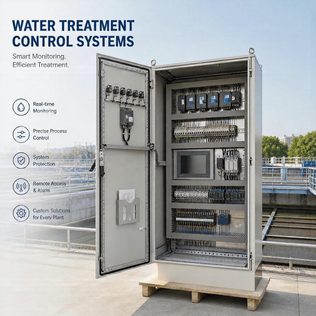
Water Treatment Control Panels
Water Treatment Control System
UniRegal supplies custom water treatment control panels for RO, UF, filtration, dosing and wastewater systems. Each panel is developed around the approved treatment process, equipment list, instrument signals, valve sequence, interlocks, alarm response and project handover requirements.
Specifications
- Application
- Custom Industrial Automation
- Control Method
- PLC / Relay Based
- Voltage
- 220V / 380V / 480V Available
- Protection Rating
- IP54 / IP65 Optional
- Communication Protocol
- Modbus / Profinet / Ethernet/IP
- Testing
- FAT Before Shipment
- Customization
- Available
Product Positioning:
Process-based control panels for water treatment OEMs, EPC contractors, system integrators and industrial facilities.
Water Treatment Control Panels Designed Around the Treatment Process
A water treatment control panel coordinates pumps, valves, filters, dosing equipment and instruments according to an approved treatment sequence. The correct panel must reflect how water moves through the system, which conditions permit each stage to run, and how the process responds when pressure, flow, level or water-quality signals become abnormal.
UniRegal supplies custom water treatment control panels for:
- Reverse osmosis systems
- Ultrafiltration systems
- Sand, carbon and multimedia filtration
- Chemical dosing systems
- Industrial wastewater treatment
- Pump and tank control
- Containerized treatment plants
- Skid-mounted water treatment equipment
- Existing system retrofit projects
Control scope: Relay, PLC, HMI, VFD and remote interfaces
Process inputs: Flow, pressure, level, conductivity, pH, ORP and equipment status
Project basis: P&ID, equipment list, instrument list and sequence of operation
Verification: Drawing review, I/O testing and sequence-based FAT
Quick Answer: What Is a Water Treatment Control Panel?
A water treatment control panel operates and monitors the electrical equipment within a treatment process. It receives information from field instruments, checks operating permissives, starts equipment in the required order, controls valves and dosing systems, displays process conditions and initiates the approved response when an abnormal condition occurs.
The panel does not determine the treatment process by itself. Its function is to translate the approved process design into repeatable electrical and automation actions.
A complete specification therefore requires more than voltage and motor power. It should identify:
- The treatment process and design capacity
- The equipment controlled by the panel
- The field instruments and signal types
- The automatic operating sequence
- The permissives, trips and alarm actions
- The manual operating boundary
- The interface with other panels or systems
- The documents and tests required before shipment
Buyer Decision Information
Start with the Treatment Process, Not the Cabinet
Buyer Situation | Information That Should Be Defined First | Appropriate Panel Direction |
|---|---|---|
Packaged RO system | Startup, shutdown, flushing, pressure protection and conductivity response | RO control panel |
UF treatment skid | Filtration, backwash, valve switching, air scour and CEB sequence | UF control panel |
Sand or carbon filtration | Service, rinse and backwash modes with valve positions | Filter control panel |
Chemical addition system | Dosing basis, chemical level, no-flow interlock and calibration method | Chemical dosing control panel |
Wastewater process | Tank levels, pumps, blowers, mixers, dosing and process timing | Wastewater control panel |
Several independent treatment skids | Interface signals, operating authority and common alarms | PLC/HMI integration panel |
Existing plant with obsolete controls | Existing sequence, field devices, shutdown window and migration plan | Retrofit water treatment panel |
Containerized treatment package | Complete equipment, environmental and field-connection boundary | Containerized system panel |
The product name alone is not enough for accurate quotation. Two RO panels with the same motor load may require different control scopes because their pretreatment, flushing method, instruments, tank arrangement and external interfaces are different.
The Five Documents That Define a Water Treatment Control Panel
A useful control-panel quotation should be based on process information rather than a general equipment list.
1. Process Flow Diagram or P&ID
The P&ID shows how water, chemicals, pumps, filters, membranes, tanks, valves and instruments are connected. It helps identify which equipment must operate together and which process conditions affect each stage.
2. Equipment List
The equipment list should identify every controlled pump, blower, mixer, dosing pump, heater, valve and auxiliary device, together with its electrical rating and operating duty.
3. Instrument List
The instrument list defines tag numbers, measurement ranges, signal types, power requirements and alarm setpoints for pressure, flow, level, conductivity, pH, ORP and other measurements.
4. Sequence of Operation
The sequence explains how the system starts, produces treated water, changes operating modes, flushes, backwashes, stops and recovers after an alarm or power interruption.
5. Cause-and-Effect Matrix
The cause-and-effect matrix connects each process condition to a required action.
Process Condition | Example Panel Response |
|---|---|
Feed tank low level | Stop feed or high-pressure pump |
Product tank high level | Complete the approved shutdown sequence |
Feed pressure unavailable | Prevent high-pressure pump start |
High discharge pressure | Stop affected equipment and generate alarm |
Conductivity above limit | Alarm, divert product water or stop production as specified |
UF differential pressure high | Request or initiate the approved cleaning sequence |
Chemical tank low level | Alarm and inhibit associated dosing if required |
No process flow | Stop or inhibit flow-paced dosing |
Valve position not confirmed | Prevent the next process step |
Instrument signal invalid | Enter the approved fallback state and notify the operator |
The matrix should identify alarm delays, reset conditions and whether the system restarts automatically or requires operator acknowledgement.
Define the Control Boundary Before Comparing Quotations
One of the most important purchasing decisions is establishing what the control-panel supplier is responsible for and what remains with the treatment-system designer, instrument supplier or commissioning team.
Project Item | Responsibility to Confirm |
|---|---|
Treatment capacity and water-quality target | Process designer or system supplier |
Membrane, filter and chemical selection | Process designer or equipment supplier |
Pump and valve sizing | Mechanical or process designer |
P&ID and equipment tags | Buyer, EPC or process designer |
Control sequence | Buyer-provided, jointly developed or panel-supplier scope |
Electrical design | Panel supplier according to approved requirements |
PLC and HMI programming | Included only when stated in the quotation |
Field instruments | Buyer supply, panel-supplier supply or mixed scope |
Instrument calibration | Factory, site or instrument-supplier scope |
Field cables and installation | Confirmed separately |
SCADA integration | Panel side only or complete plant integration |
Hydraulic commissioning | Process or site commissioning team |
Final process setpoints | Approved by the process designer |
Water-quality performance | Depends on the complete treatment process, not the panel alone |
A panel supplier can implement the approved process logic, but the control panel alone cannot guarantee flow capacity, membrane recovery, chemical consumption or treated-water quality.
RO Water Treatment Control Panels
An RO control panel must coordinate the complete operating sequence surrounding the membrane system. Starting the high-pressure pump is only one part of that sequence.
Typical RO Operating Stages
Standby
The panel monitors tank levels, equipment availability and external demand while the production sequence remains stopped.
Pre-Start Check
Before starting production, the system checks the required tank levels, valve positions, feed availability, alarm status and pump permissives.
Low-Pressure Flushing
Where required by the approved membrane-system design, low-pressure water removes air and flushes the system before normal pressurization. Valve positions and drain routing must be confirmed before the next stage.
Production
Feed and high-pressure pumps operate according to the approved sequence. The panel monitors pressure, flow, tank level, conductivity and relevant dosing interlocks.
Normal Shutdown
A controlled shutdown may stop dosing, remove pressure and initiate flushing before the system returns to standby.
Alarm Shutdown
The response depends on the alarm. Some conditions require an immediate stop, while others allow a controlled sequence or product-water diversion.
RO Control Decisions
Control Item | Buyer Must Define |
|---|---|
Production Demand | Product-tank level, external command or schedule |
Feed Permissive | Feed-tank level, inlet pressure or feed-pump confirmation |
High-Pressure Pump Start | Required valve positions, pressure and flow conditions |
Pressurization | Start order, ramp time and applicable delays |
Flushing | Trigger, valve sequence, duration and destination |
Conductivity Response | Alarm, diversion, shutdown or monitoring only |
Dosing Interlock | Feed flow, pump status or production mode |
Product Tank Full | Immediate stop or controlled shutdown |
Restart After Alarm | Automatic, delayed or manual reset |
Restart After Power Return | Hold, resume sequence or operator acknowledgement |
The membrane supplier’s operating limits and approved startup procedure should take precedence over a generic control sequence.
UF Water Treatment Control Panels
UF operation is sequence-based because the same membrane system changes between filtration, backwash, rinse, air scour and chemically enhanced backwash modes.
The panel must coordinate pumps and valves while verifying that incompatible flow paths are not open at the same time.
Typical UF Sequence Requirements
Operating Mode | Control Requirement |
|---|---|
Filtration | Confirm filtration valve path and feed conditions |
Backwash | Stop or redirect filtration before changing valve positions |
Valve Transition | Allow the required movement time and verify feedback |
Air Scour | Coordinate blower or compressed-air permissives |
Drain | Open the approved drain route before the next step |
Forward Flush | Establish the defined flushing path and flow |
Chemically Enhanced Backwash | Coordinate chemical selection, dosing, soaking and rinsing |
Clean-in-Place | Follow the separately approved CIP sequence |
Return to Service | Confirm chemical removal and correct valve alignment |
Why Valve Feedback Matters
A timer can issue an open or close command, but it does not prove that a motorized or pneumatic valve reached the required position. Where valve position affects membrane protection or chemical routing, open and closed feedback should be considered.
The control sequence should define what happens when a valve fails to reach position within the permitted time. The next process step should not begin automatically unless the required flow path has been confirmed.
Filter and Backwash Control Panels
Sand, carbon and multimedia filters normally alternate between service, backwash, rinse and return-to-service modes.
Backwash may be initiated by:
- Elapsed operating time
- Differential pressure
- Treated volume
- Operator command
- A plant-level control request
- A combination of these conditions
Information Required for Filter Automation
Design Question | Why It Matters |
|---|---|
What initiates backwash? | Defines the primary control trigger |
Can multiple filters backwash simultaneously? | Determines sequence coordination and utility demand |
Is a backwash pump shared? | Requires equipment reservation and interlocking |
Is air scour included? | Adds blower and valve coordination |
Which valves have position feedback? | Determines sequence verification |
Where is backwash water discharged? | Confirms the correct drain path |
What returns the filter to service? | Defines rinse completion and availability |
What happens if a valve fails? | Defines hold, alarm and manual recovery |
For multi-filter systems, the panel may need to queue backwash requests so that one unit cleans while the remaining filters stay available.
Chemical Dosing Control Panels
Chemical dosing should be controlled according to a defined process basis. Running a dosing pump whenever the panel is energized does not confirm that the correct amount of chemical reaches the process.
Common Dosing Methods
Dosing Method | Suitable Situation | Required Input |
|---|---|---|
Manual Rate | Fixed operator-selected output | Local setting |
Timer-Based | Periodic chemical addition | Time schedule |
Flow-Paced | Dose changes with water flow | Flow-meter pulse or analog signal |
Ratio Control | Chemical feed follows a defined flow ratio | Flow and dosing calculation |
Feedback Control | Dose responds to pH, ORP or another measured value | Valid analyzer signal |
Batch or Recipe Control | Defined quantity for a specific process stage | Batch command and sequence data |
Dosing Interlocks to Confirm
The buyer should define whether dosing stops when:
- Process flow is unavailable
- The associated pump stops
- The chemical tank reaches low level
- The dosing pump reports a fault
- The analyzer signal becomes invalid
- The treatment system leaves production mode
- A valve or process permissive is unavailable
The panel should also define whether loss of an analyzer signal stops dosing, holds the last output, changes to a manual value or only generates an alarm. This decision depends on the chemical and treatment process.
Calibration Responsibility
A command such as 50% speed does not prove actual chemical delivery. Dosing pumps may require calibration against the installed suction and discharge conditions. The quotation should state whether calibration equipment, pump commissioning and verification of actual dosing output are included.
Wastewater Treatment Control Panels
Wastewater control panels often coordinate several connected processes rather than one packaged skid. The control scope may include lift pumps, transfer pumps, blowers, mixers, dosing pumps, sludge equipment, tank levels and analytical instruments.
The key purchasing question is where the automation boundary begins and ends.
Typical Control Areas
Process Area | Typical Control Requirement |
|---|---|
Collection or Equalization | Level control, pump alternation and high-level alarm |
Aeration | Blower operation, timing or dissolved-oxygen control |
Mixing | Equipment permissives and runtime sequence |
Chemical Treatment | Flow-paced or feedback dosing |
Clarification | Sludge pump timing and equipment coordination |
Sludge Handling | Pump, mixer and level interlocks |
Treated-Water Discharge | Flow monitoring and water-quality permissives |
Remote Station | Local autonomous operation and SCADA reporting |
Where several remote panels are connected to a plant SCADA system, each local panel should have a clearly defined response to communication failure. Plant operation should not depend on an undefined network condition.
Water-Quality Instruments and Signal Handling
The panel may receive signals from:
- Conductivity or TDS transmitters
- pH and ORP analyzers
- Turbidity instruments
- Chlorine or disinfectant analyzers
- Flow meters
- Pressure transmitters
- Differential-pressure transmitters
- Level transmitters and switches
- Temperature instruments
- Pump and valve status contacts
Information Required for Every Instrument
Instrument Detail | Example of Required Definition |
|---|---|
Tag Number | PIT-101, FIT-201 or project-specific tag |
Measurement Range | Approved engineering range |
Signal Type | 4–20 mA, pulse, dry contact or communication |
Power Supply | Loop-powered or separate supply |
Engineering Units | bar, psi, m³/h, GPM, µS/cm or project units |
Normal Operating Range | Expected process value |
Alarm Setpoints | High, high-high, low or low-low |
Alarm Delay | Immediate or time-filtered |
Control Use | Display only, interlock, PID or shutdown |
Signal Failure Action | Alarm, hold, fallback or shutdown |
Calibration Scope | Factory, site or instrument supplier |
Instrument range and PLC scaling must match. A correct electrical signal with an incorrect configured range can display a believable but wrong process value.
Permissives, Interlocks, Trips and Alarms Are Not the Same
These terms should be separated in the control narrative.
Permissive
A condition that must be healthy before equipment is allowed to start. For example, an RO high-pressure pump may require feed availability and the correct valve path.
Interlock
A control relationship that prevents incompatible equipment states or coordinates one device with another.
Trip
An action that stops equipment when the defined condition requires shutdown.
Alarm
A message requiring operator awareness or action. An alarm does not automatically mean that the associated equipment must stop.
The alarm list should state the alarm text, trigger condition, delay, equipment action, reset method and remote reporting requirement. Generic messages such as “System Fault” provide little help during commissioning or operation.
HMI Design for Water Treatment Operators
The HMI should help an operator understand the treatment process without relying on the PLC programmer.
A practical water treatment HMI may include:
Process Overview
Shows the current operating mode, water path, major equipment status and important process measurements.
Equipment Detail
Shows manual/automatic mode, start permissives, running status, fault condition, runtime and available commands for each equipment group.
Instrument Display
Shows the measured value, units, alarm limits, signal status and relevant trend where required.
Sequence Status
Shows whether the system is in standby, flushing, production, backwash, CEB, shutdown or another defined mode.
Alarm Information
Identifies the affected equipment, the process condition, the automatic action already taken and the reset requirement.
Maintenance Controls
Provides authorized access to timers, setpoints, calibration values and equipment tests without exposing critical parameters to unrestricted changes.
Access levels and editable values should be agreed before programming. Setpoints that protect membranes, chemicals or equipment should not be treated as ordinary operator adjustments.
Manual Mode Must Have a Defined Boundary
Manual operation is useful during installation, maintenance and troubleshooting, but it should not silently bypass every process safeguard.
The control philosophy should define:
- Which devices may be operated manually
- Which protective trips remain active
- Whether valve sequence interlocks remain active
- Whether manual equipment can run during an automatic sequence
- How the HMI indicates manual operation
- Whether remote commands are blocked
- How the system returns to automatic mode
A manual command should not create an undefined process state. If commissioning requires temporary override of an interlock, the override method, indication and removal procedure should be controlled.
Integration with Skids, MCCs and Plant Systems
Water treatment projects often divide control between packaged equipment and plant-level systems.
Package Control Panel
Controls the process equipment supplied within one RO, UF, dosing or filtration package.
Pump Control Panel
Controls pumps according to pressure, level, flow and lead-lag requirements. See Pump Control Panels for pump-specific operating decisions.
MCC Panel
Distributes power and provides motor feeders for multiple equipment groups. See MCC Panels for feeder structure, isolation and maintenance planning.
PLC Control Panel
Provides a general automation platform based on I/O, control logic, HMI and communication requirements. See PLC Control Panels for software ownership and platform-selection decisions.
Plant SCADA
Provides supervisory monitoring, historical data, reporting and remote commands across multiple treatment areas.
The interface schedule should state which system owns each command, status, alarm and setpoint. Duplicate control authority between a local panel and SCADA can create conflicting commands during commissioning.
Build-to-Print or Process-Based Design
Build-to-Print
Build-to-print is suitable when the buyer already has approved electrical drawings, panel layout, BOM, I/O list, terminal schedule and software requirements.
The quotation should identify whether UniRegal is responsible only for manufacturing and testing against the supplied documents or also for reviewing design inconsistencies.
Process-Based Custom Design
Process-based design is suitable when the buyer has the treatment process and equipment information but needs the panel architecture, electrical drawings or control sequence to be developed.
Typical starting documents include:
- P&ID or process flow diagram
- Equipment list
- Motor and load schedule
- Valve list
- Instrument list
- Functional description
- Alarm requirements
- Site electrical information
- Communication requirements
- Preferred component brands
The final sequence, drawings and supply boundary should be approved before production.
Control Panel Retrofit and Replacement
A retrofit project starts with understanding how the existing plant operates, including any field modifications that were never added to the original drawings.
Useful information includes:
- Clear internal and external panel photographs
- Existing electrical drawings
- PLC, HMI and VFD model numbers
- Program backups where available
- Instrument and equipment lists
- Field voltage and signal information
- Current alarm and operating descriptions
- Known changes made after installation
- Permitted shutdown duration
- Required reuse of field cables or instruments
Retrofit Decisions
The buyer should determine whether the project requires:
- Like-for-like panel replacement
- Obsolete-component replacement
- PLC and HMI migration
- Rewiring of existing instruments
- New process instruments
- Revised alarm messages
- New communication with SCADA
- Staged migration to limit shutdown time
- Temporary operation during replacement
The new panel should not reproduce undocumented behavior without review. Existing logic must be compared with the current treatment requirement before it is transferred.
What UniRegal Supplies
Depending on the confirmed project scope, UniRegal can provide:
- Review of P&IDs and equipment information
- Control-boundary clarification
- Electrical schematic development
- Panel layout and component schedule
- PLC and HMI hardware integration
- Control programming according to approved logic
- VFD and field-instrument interfaces
- Panel assembly and internal wiring
- Terminal, wire and equipment identification
- Factory I/O and sequence testing
- Electrical and automation documentation
- Export packing
- Remote technical coordination
Field installation, instrument supply, calibration, SCADA modification, process commissioning and on-site services are identified separately in the quotation.
Factory Acceptance Testing Based on the Process Sequence
Water treatment panel FAT should verify more than power-on operation. The test should follow the approved sequence and cause-and-effect matrix.
Typical FAT Scope
- Component and BOM verification
- Panel layout and workmanship inspection
- Protective-earth and wiring checks
- Control-power verification
- Digital input and output simulation
- Analog-signal injection and scaling checks
- Pump and motor-command simulation
- Valve command and feedback simulation
- Startup and shutdown sequence testing
- RO flushing and production-mode simulation
- UF filtration and backwash sequence simulation
- Dosing interlock checks
- Permissive and trip verification
- Instrument signal-loss testing
- Alarm text, delay and reset checks
- Manual and automatic mode checks
- HMI navigation and access-level checks
- Communication-point testing where included
- Power-restoration response
- Program and parameter backup
What FAT Can Verify
Factory testing can verify whether the panel receives simulated signals, follows the approved logic, issues the correct commands and displays the required alarms.
What FAT Cannot Fully Verify
FAT cannot reproduce actual membrane pressure, filter loading, water chemistry, pump curves, valve travel under site conditions, analyzer performance or treated-water quality. Final control setpoints, PID adjustment, dosing calibration and process acceptance normally require site commissioning with the complete water treatment system.
This boundary should be stated clearly before order.
Documents Available for Approval and Handover
Depending on the agreed scope, the documentation package may include:
- General arrangement drawing
- Electrical schematic
- Panel layout
- Bill of materials
- I/O list
- Terminal schedule
- Field connection diagram
- Instrument signal list
- Network architecture
- Sequence of operation
- Cause-and-effect matrix
- Alarm and interlock list
- HMI screen list
- PLC hardware configuration
- Software and parameter backups
- FAT checklist or test report
- Operation and maintenance information
- Packing list
Revision status should be controlled so that the drawings, program and panel supplied at shipment represent the same approved configuration.
How to Compare Water Treatment Control Panel Quotations
A lower cabinet price may exclude the engineering work required to make the treatment system operate correctly. Before comparing quotations, check whether each supplier has included:
Quotation Item | Question to Ask |
|---|---|
Process Review | Has the supplier reviewed the P&ID and sequence? |
Control Logic | Is programming included, and who approves the sequence? |
I/O Scope | Are all instruments, valves and remote signals counted? |
Analog Signals | Are scaling, isolation and signal-loss actions included? |
HMI | How many screens, alarms and editable setpoints are included? |
Communication | Is the scope hardware only or complete data mapping? |
Instruments | Are field instruments included or panel interfaces only? |
Valve Control | Are commands and position feedback both included? |
Documentation | Which drawings and schedules are provided? |
FAT | Is testing limited to wiring, or does it include sequence simulation? |
Software | Will editable source files and backups be handed over? |
Commissioning | Is remote or on-site support included? |
Certification | Which standard or third-party requirement is confirmed? |
Retrofit | Who verifies existing signals and undocumented changes? |
A technically complete comparison separates panel manufacturing, process review, programming, instruments, integration, FAT and site services instead of treating them as one undefined item.
Typical Technical Configuration
All ratings and brands are selected according to approved project requirements.
Item | Project-Defined Options |
|---|---|
Application | RO, UF, filtration, dosing, wastewater or combined process |
Control Architecture | Relay, PLC, PLC with HMI or plant interface |
Incoming Supply | Project-defined voltage, phase and frequency |
Motor Control | Contactor, overload relay, soft starter or VFD |
Digital Signals | Dry contact or project-defined control voltage |
Analog Signals | 4–20 mA, 0–10 V, RTD, pulse or project-specific |
Communication | Hardwired, Modbus, Ethernet or approved protocol |
Installation | Indoor, outdoor, containerized or skid-mounted |
Enclosure | Wall-mounted or floor-standing |
Environmental Protection | Project-defined IP or NEMA requirement |
Documentation | Drawings, I/O, terminals, logic and test records |
Testing | Inspection, I/O verification and sequence FAT |
Applicable assembly standards, enclosure approvals, short-circuit ratings and third-party certification must be stated in the enquiry and confirmed in the quotation.
Information Required for a Quotation
Treatment Process
- RO, UF, filtration, dosing, wastewater or combined system
- Design flow rate
- Process flow diagram or P&ID
- Description of normal operation
- Required operating modes
Controlled Equipment
- Pump and motor list
- Blowers and mixers
- Dosing pumps
- Solenoid, pneumatic and motorized valves
- Heaters or auxiliary loads
- Equipment voltage and full-load current
Instruments
- Instrument tag and function
- Measurement range
- Signal type
- Power requirement
- Alarm setpoints
- Control or display purpose
Automation
- Required PLC and HMI
- Sequence of operation
- Cause-and-effect requirements
- Manual and automatic modes
- SCADA or remote-system interface
- Communication protocol
- Software handover requirement
Installation
- Indoor, outdoor or containerized location
- Ambient temperature
- Humidity and condensation conditions
- Dust or chemical exposure
- Enclosure material and protection requirement
- Cable entry and mounting method
Project Deliverables
- Required drawings
- FAT procedure
- Documentation standard
- Certification requirement
- Delivery schedule
- Site commissioning responsibility
Incomplete information does not always prevent quotation, but assumptions should be listed clearly and resolved before drawings and programming are approved.
Frequently Asked Questions
What is the difference between a water treatment control panel and a pump control panel?
A pump control panel focuses on pump operation according to pressure, level, flow and duty requirements. A water treatment control panel coordinates the broader treatment sequence, which may include pumps, valves, membranes, filters, dosing systems, water-quality instruments, flushing, backwashing and SCADA interfaces.
Can a water treatment control panel guarantee the required treated-water quality?
No. The panel can operate equipment, monitor instruments and respond according to approved logic, but final water quality also depends on feedwater analysis, process design, membrane or media selection, chemical treatment, equipment sizing, instrument condition and site commissioning.
Who should provide the sequence of operation?
The buyer, EPC or treatment-system designer may provide an approved sequence, or sequence development may be included in the panel supplier’s scope. In either case, the party responsible for process performance should review and approve the final sequence before programming and FAT.
Can you quote if we only have a P&ID and equipment list?
A preliminary configuration can be developed from these documents, but instrument signals, valve feedback, alarm actions, operating modes and the control boundary still need confirmation. Assumptions should be recorded so that they do not become undocumented logic during production.
How is an RO or UF sequence tested without operating the actual water system?
During FAT, field signals are simulated to verify permissives, valve commands, pump commands, operating modes, timers, alarms and shutdown responses. Actual hydraulic behavior, membrane performance, analyzer response and final process settings must be verified during site commissioning.
Should every motorized valve have open and closed feedback?
Not necessarily. Feedback is most important when the next process step depends on confirmed valve position or when an incorrect flow path could affect equipment, chemicals or product water. The P&ID and control narrative should identify which valve positions must be proven.
What happens if a pH, conductivity or flow signal fails?
The required action must be defined for each instrument. Depending on its function, the system may generate an alarm, stop dosing, divert water, hold a controlled output, continue in a limited mode or shut down. The panel supplier should not assume one universal response.
Can manual mode bypass process interlocks?
Only where the approved control philosophy permits it. Equipment protection and critical process conditions should normally remain active. Any maintenance override should be visible, access-controlled and removed before the system returns to normal automatic operation.
Are field instruments included with the control panel?
They can be included when specified, but many projects supply instruments separately. The quotation should distinguish the physical instrument, mounting accessories, analyzer, field cable, panel interface, configuration, calibration and site commissioning responsibilities.
Can the panel connect to an existing SCADA system?
Yes, provided the protocol, network architecture, address structure and data-point list are available. The quotation should state whether UniRegal supplies only the panel-side communication interface or also performs SCADA database, graphics and site-integration work.
What information is required for a retrofit panel?
Please provide panel photographs, available drawings, PLC and HMI models, program backups, instrument details, motor data, field voltages, current operating descriptions and the permitted shutdown duration. Site modifications that are not shown in the original drawings should also be identified.
What should be included in the FAT documentation?
The FAT package should reference the approved drawings, I/O list, sequence and cause-and-effect matrix. Test records should show which inputs, outputs, operating modes, alarms, interlocks and communication points were verified, together with any open items requiring site confirmation.
Request a Water Treatment Control Panel Quotation
Send UniRegal your P&ID, equipment list, instrument list, motor data, valve schedule, operating sequence, I/O requirements and installation conditions.
We review how the treatment process should operate before finalizing the panel configuration. This allows the proposal to define the electrical scope, process interfaces, control logic, alarm response, documentation and FAT boundary instead of providing only a cabinet price.
We confirm receipt within 24 hours and advise the next technical step within 1–2 business days, depending on project complexity.
Related products:
Related Industrial Page: